Method for handover problem identification

a problem identification and problem technology, applied in the field of handover problem identification, can solve the problems of radio link failure, and resource-consuming ho procedure, and achieve the effect of reducing the cost of network resources, unnecessary hos and inefficient consumption of network resources

Inactive Publication Date: 2012-04-12
HUAWEI TECH CO LTD
View PDF4 Cites 48 Cited by
  • Summary
  • Abstract
  • Description
  • Claims
  • Application Information

AI Technical Summary

Benefits of technology

[0041]There are other approaches that have been proposed that are similar to the ones described above. For instance, other approaches proposing to use UE History (or something similar) to determine handover success / failure rates, in effect implementing a relatively simple HO failure counter approach.

Problems solved by technology

Due to fast movement and inadequate HO parameter setting, the UE leaves the source cell coverage before the HO is triggered.
When the UE exits the island of coverage of the target cell, it cannot acquire the target cell anymore and the HO fails, potentially leading to a radio link failure.
HO procedure is resource-consuming and therefore costly to the network operator.
Sometimes, the combination of user mobility patterns and cell coverage boundary layout can generate frequent unnecessary HOs that consume network resources inefficiently.
However, a main drawback with this approach is that confidence in the handover settings can only be gained by capturing the results of a large number of handovers.
Furthermore, it is difficult to extrapolate the measurements to handle future changes to the environment that may impact handover performance—examples are UE speed, locations of handover between the two cells, UE Discontinuous Reception, DRX, settings.
In conclusion, this is quite a crude measurement and only provides limited information to the SON entity.
Disadvantages with this approach, similar to those of the early / late counters, handover failure with early / late identification, are that the Self Organising Network, SON, entity must be reactive not pro-active.
However, the method does not address the performance of real handovers; it is based upon a number of assumptions which introduce inaccuracies.
However, still there is no catch-all solution and therefore improved methods in view of solving this problem are needed.

Method used


Image

  • Method for handover problem identification
  • Method for handover problem identification
  • Method for handover problem identification

Examples


Embodiment Construction

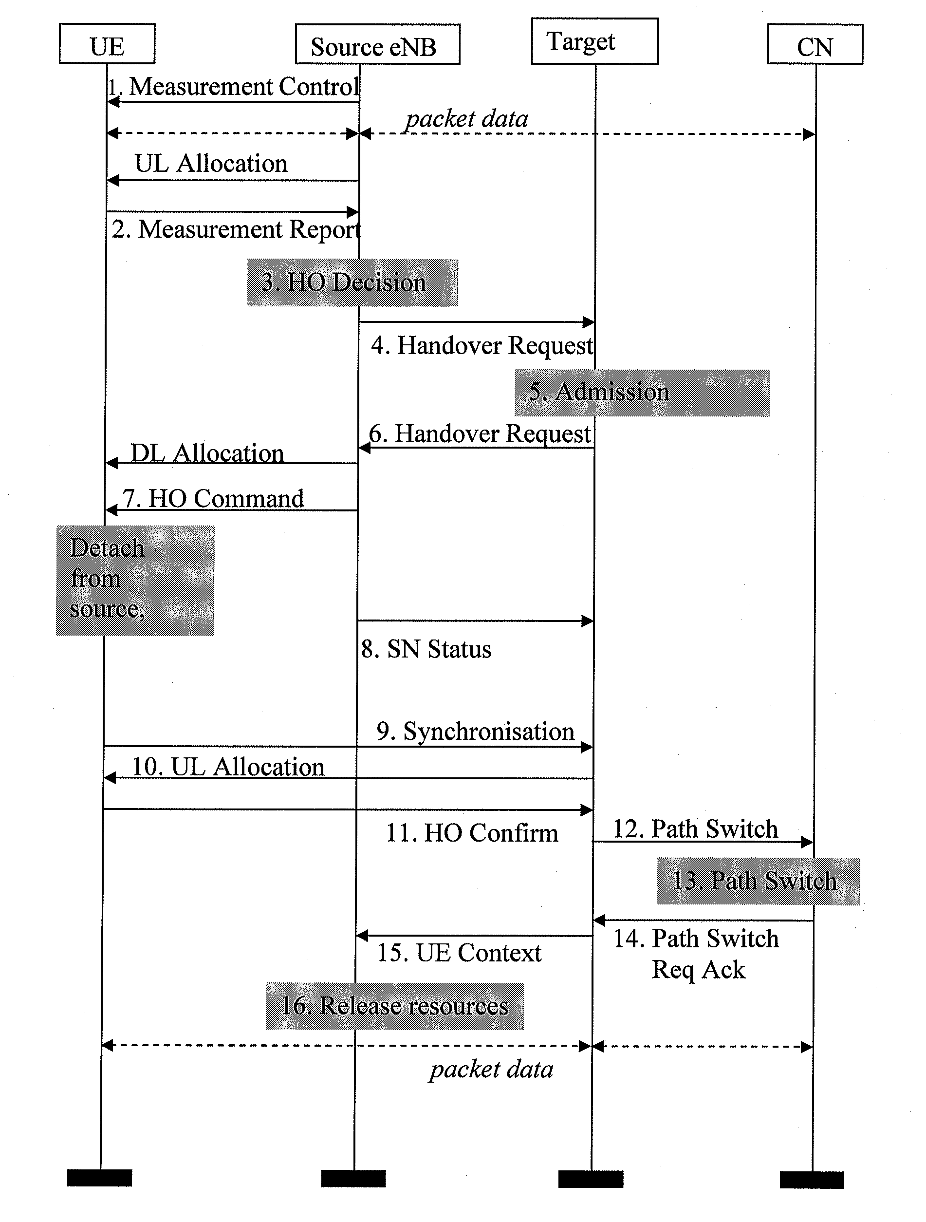
[0094]A preferred embodiment represents a means to identify and correct non-ideal handover behaviour, for instance in the E-UTRAN. The solution takes one or more measurements of the radio conditions between the mobile terminal and the target and source cells for successful handovers. Measurement(s) is (are) taken at the end of the handover execution and optionally at the trigger point and optionally at intervals following the handover. Several measurements (pertaining to a particular handover, e.g. cell A to cell B) can be gathered at one point to facilitate analysis. As a result of an optimisation procedure on the analysed results, the handover parameters governing the particular handover may be changed. The method aims to proactively adjust the handover parameters towards an optimum point. This can, for example, eliminate handovers failing in a too-early fashion. The solution to the problem thus may comprise the following steps:

1. measurement capture on successful handovers

2. meas...


PUM


Abstract

Method for handover problem identification in a mobile telecommunications system, the system including at least a first radio basestation, a second radio basestation and a mobile terminal able to communicate with said basestations, said mobile terminal is adapted to do a handover from the first basestation to the second basestation, the method including the steps of:
    • take at least one measure of a link quality between the terminal and any of the stations,
    • evaluate any measure of a link quality in regard of handover problem identification,
The invention is distinguished by:
  • in the step of taking the at least one measure, take said at least one measure of a link quality at an end of a successful handover execution of the mobile terminal from the first basestation to the second basestation. The invention also comprises a mobile terminal, a radio basestation and a management entity.
  • Description

    CROSS-REFERENCE TO RELATED APPLICATIONS[0001]This application is a continuation of International Application No. PCT / CN2009 / 071391, filed on Apr. 21, 2009, which is hereby incorporated by reference in its entirety.FIELD OF THE INVENTION[0002]The present invention concerns a method for handover problem identification in a mobile telecommunications system. Further, it concerns a mobile terminal for a mobile telecommunications system, a radio basestation for a mobile telecommunications system and a management entity for a mobile telecommunications system.BACKGROUND ART[0003]The context of the background art (and the invention) is a cellular wireless network system. Such a system may include at least a first radio basestation and a second radio basestation which are able to communicate with a mobile terminal. Further, the mobile terminal is adapted to do a handover from the first basestation to the second basestation, meaning that the mobile terminal can switch communication from the fi...

    Claims


    Application Information

    Patent Timeline
    Patent Type & Authority Applications(United States)
    IPC IPC(8): H04W36/30H04W24/00
    CPCH04W36/245H04W36/008375
    Inventor LEGG, PETERJOHANSSONOLOFSSON, HENRIK
    Owner HUAWEI TECH CO LTD
    Why Eureka
    Try Eureka