Network switching method, device and system, switching determination method and device

A network and post-handover technology, which is applied in the field of handover determination methods and devices, can solve problems such as inability to determine network handover failures, and achieve the effects of improving handover efficiency and reducing handover failures

Active Publication Date: 2021-11-30
ZTE CORP
View PDF7 Cites 0 Cited by
  • Summary
  • Abstract
  • Description
  • Claims
  • Application Information

AI Technical Summary

Problems solved by technology

[0023] Embodiments of the present invention provide a network switching method, device, and system, as well as a switching determination method and device, to at least solve the problem in the related art that the source network cannot be determined when switching due to the fact that the target base station can connect to two networks of different network standards at the same time. The problem of network switching failure caused by the later connected network

Method used


Image

  • Network switching method, device and system, switching determination method and device
  • Network switching method, device and system, switching determination method and device
  • Network switching method, device and system, switching determination method and device

Examples


Embodiment 1

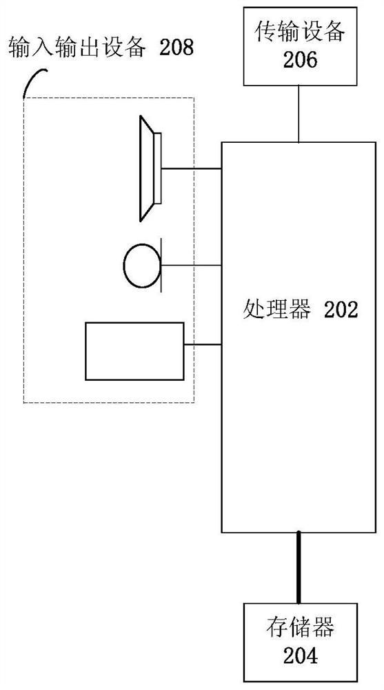
[0079] The method embodiment provided in Embodiment 1 of the present application may be executed in a mobile terminal, a computer terminal, or a similar computing device. Taking running on a mobile terminal as an example, figure 2 It is a hardware structural block diagram of a mobile terminal according to a network switching method according to an embodiment of the present invention. Such as figure 2 As shown, the mobile terminal 20 may include one or more ( figure 2 Only one is shown in the figure) processor 202 (processor 202 may include but not limited to a processing device such as a microprocessor MCU or a programmable logic device FPGA) and a memory 204 for storing data. Optionally, the above-mentioned mobile terminal also A transmission device 206 for communication functions as well as input and output devices 208 may be included. Those of ordinary skill in the art can understand that, figure 2 The shown structure is only for illustration, and does not limit the...

Embodiment 2

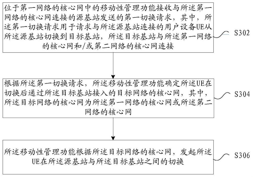
[0142] In this embodiment, a method that operates on the above-mentioned figure 2 The handover determination method of the network of the mobile terminal shown in, Figure 7 is a flow chart of a network handover determining method according to an embodiment of the present invention, as shown in Figure 7 As shown, the process includes the following steps:

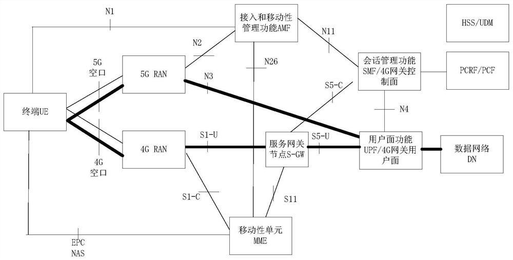
[0143] Step 702, the source base station connected to the core network of the first network receives the measurement report sent by the user equipment UE, and determines the target base station that needs to be handed over, wherein the target base station is connected to the core network of the first network and / or the second network core network connection;

[0144]Step 704, the source base station sends a first handover request to a mobility management function located in the core network of the first network, where the first handover request is used to request the UE to switch from connecting to the source base statio...

Embodiment 3

[0204] In this embodiment, a network switching device is also provided, which is used to implement the above embodiments and preferred implementation modes, and what has been described will not be repeated. As used below, the term "module" may be a combination of software and / or hardware that realizes a predetermined function. Although the devices described in the following embodiments are preferably implemented in software, implementations in hardware, or a combination of software and hardware are also possible and contemplated.

[0205] Figure 14 is a structural diagram of a network switching device according to an embodiment of the present invention, such as Figure 14 As shown, the device includes: a receiving module 1402, a determining module 1404, and a switching module 1406;

[0206] A receiving module 1402, configured to receive a first handover request sent by a source base station connected to a core network of the first network, where the first handover request i...


PUM


Abstract

The invention provides a network switching method, device and system, and a switching determination method and device. The network handover method includes: a mobility management function located in the core network of the first network receives a first handover request sent by a source base station connected to the core network of the first network, wherein the first handover request is used for requesting a user equipment UE connected to the source base station to switch from the source base station to a target base station, where the target base station is connected to the core network of the first network and / or the core network of the second network; according to the first Handover request, the mobility management function determines the core network of the target network that the UE accesses through the target base station after handover, where the core network of the target network is the core network of the first network or the The core network of the second network; the mobility management function initiates handover of the UE between the source base station and the target base station according to the core network of the target network.

Description

technical field [0001] The present invention relates to the communication field, in particular, to a network switching method, device and system, and a switching determination method and device. Background technique [0002] 3GPP (3rd Generation Partnership Project) started to formulate the fourth generation (or called LTE, Long Term Evolution, long-term evolution) mobile communication system from R8. 3GPP began to study the next generation communication system (NextGen System) from R14, and formally formulated the 5G system specification in R15. [0003] The deployment of NextGen System (5G, hereinafter referred to as 5G) will initially be deployed locally in hot spots, such as city centers and commercial centers. When the UE accesses the 5G system, as the user moves, it moves out of the coverage of the 5G system. In order to ensure the continuity of the user's business (the IP address remains unchanged), the user UE is handed over to the 4G system. [0004] figure 1 It ...

Claims


Application Information

Patent Timeline
Patent Type & Authority Patents(China)
IPC IPC(8): H04W36/00H04W36/14H04W36/08H04W48/16
CPCH04W36/0011H04W36/14H04W36/08H04W48/16H04W36/0022
Inventor 李振东朱进国
Owner ZTE CORP
Why Eureka
Try Eureka