Method for Achieving Converter Transformer for Suppressing DC Bias Magnet

a technology of dc bias magnet and transformer, which is applied in the direction of magnets, electrical appliances, magnetic bodies, etc., can solve the problems of increased noise level, increased wear and tear of the transformer itself, and increased oscillation level, so as to reduce the effect of dc magnetic bias

Active Publication Date: 2012-04-19
TBEA SHENYANG TRANSFORMER GRP CO LTD
View PDF9 Cites 3 Cited by
  • Summary
  • Abstract
  • Description
  • Claims
  • Application Information

AI Technical Summary

Benefits of technology

[0007]In view of the problems in the convention technology, the present invention is to provide a converter transformer with DC magnetic bias such that the effect of DC magnetic bias effect is decreased.
[0016]1. Decrease the disadvantageous effect of DC bias current to the transformer. According to the present invention, a resistance to DC bias magnetic flux generated by DC current is increased through reserving a width to the joint portion of the laminate units, thereby increasing the no load current of the transformer, reducing the DC magnetic bias of the transformer which includes reducing the increasingly high level of oscillation phenomenon, reducing the increase of noise level, reducing the overheat possibility of the iron core, metal structural parts and oil tank, etc. of the transformer, and even reducing the possible damage to the insulation parts.
[0017]2. Effectively reduce the harmful effect to the electric power system. In reducing the effect of DC bias current and magnetic flux to the transformer, the adverse effect and damaging effect to the electric power system due to the transformer being affected by bias current and magnetic flux are reduced.

Problems solved by technology

Due to the half cycle saturation phenomenon which is occurred in the core, a large amount of saturated magnetic flux linkage forms a closed loop path outside the core, the exciting current is distorted dramatically, thereby the transformer itself will have increased wear and tear under no load condition and increased level of oscillation, increased noised level.
In addition, the core, metal parts and oil tank of the transformer will become overheat while the insulation element will be damaged.
When the situation is serious, the electric power system will be jeopardized and the power grid may be collapsed.

Method used


Image

  • Method for Achieving Converter Transformer for Suppressing DC Bias Magnet
  • Method for Achieving Converter Transformer for Suppressing DC Bias Magnet
  • Method for Achieving Converter Transformer for Suppressing DC Bias Magnet

Examples


exemplary embodiment 1

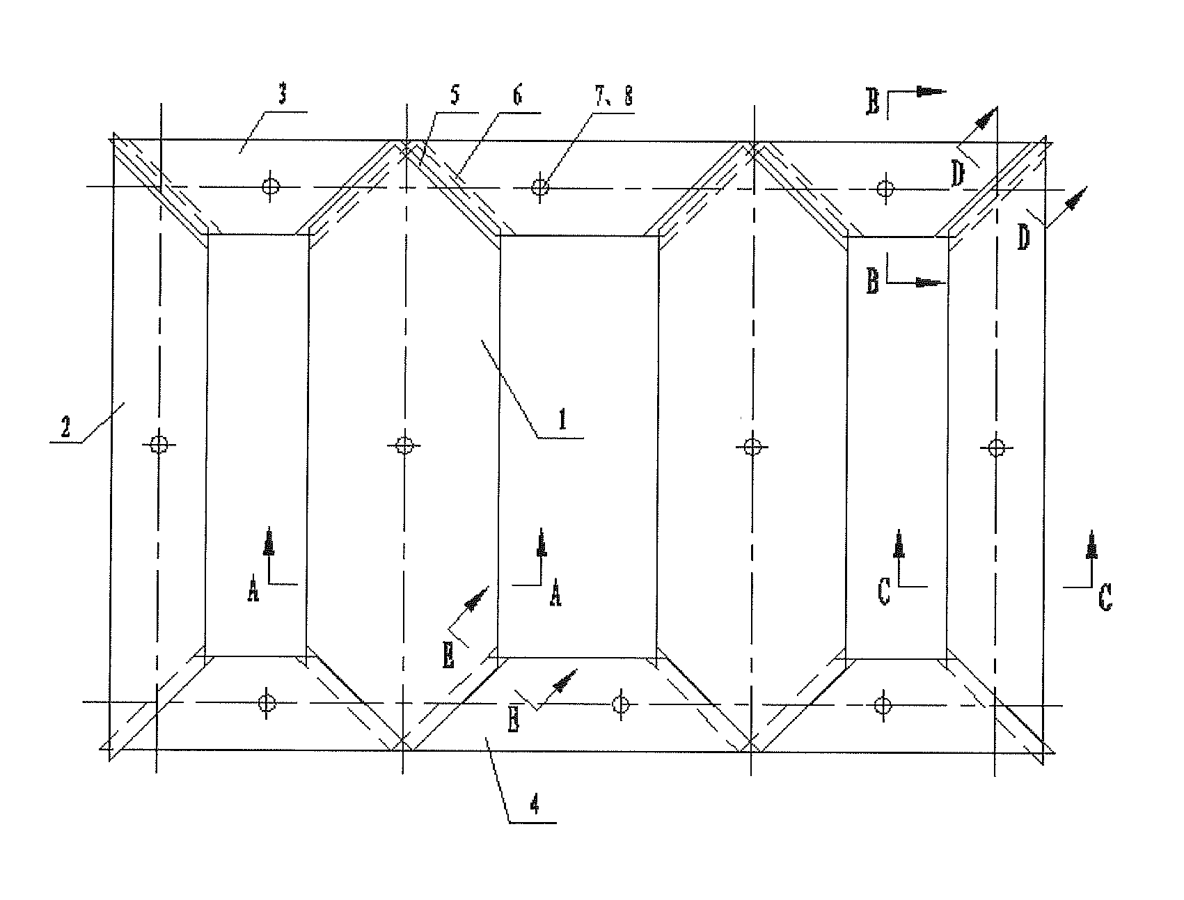
[0031]According to the preferred embodiment of the present invention, the method is applied in a transformer with an iron core unit and side column so as to increase a width of a joint portion (seaming width) of each laminate unit of the core unit of the transformer (transformer core lamination). In particular, the method comprises the following steps:

[0032]defining a preset number of levels (stages) for the iron core unit, determining a width and a height of the laminate unit for each of the levels of the iron core unit through computing a reserved width of the joint portions of the laminate units, a cross-section of the core unit, a column spacing between the columns of the core unit and a height of a window of the core unit;

[0033]cutting each of the laminate units according to the width and the height of each of the laminate units obtained from the above step;

[0034]aligning the laminate units in such a manner that one of the laminate units of each of the levels are overlapped and...

embodiment 2

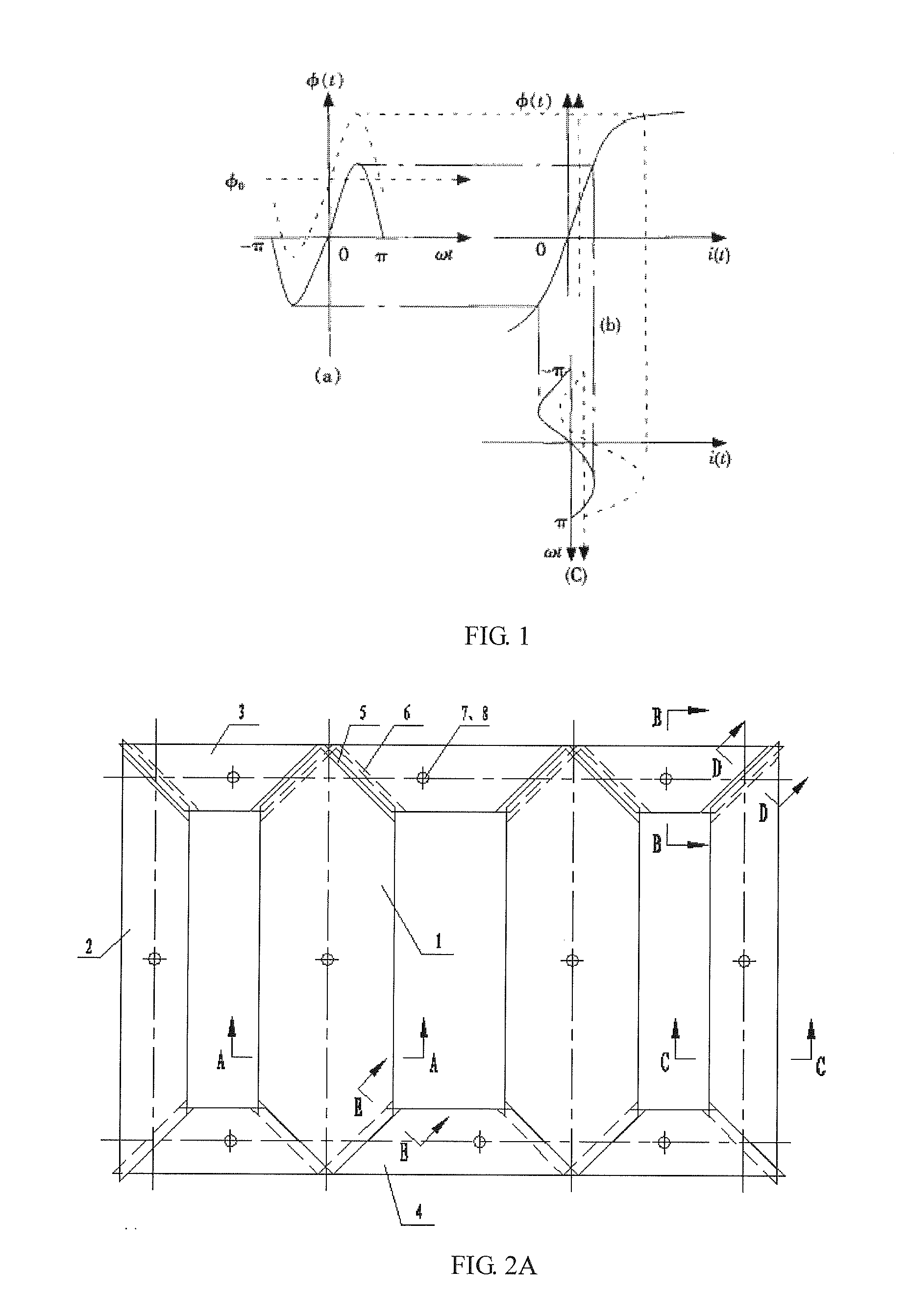
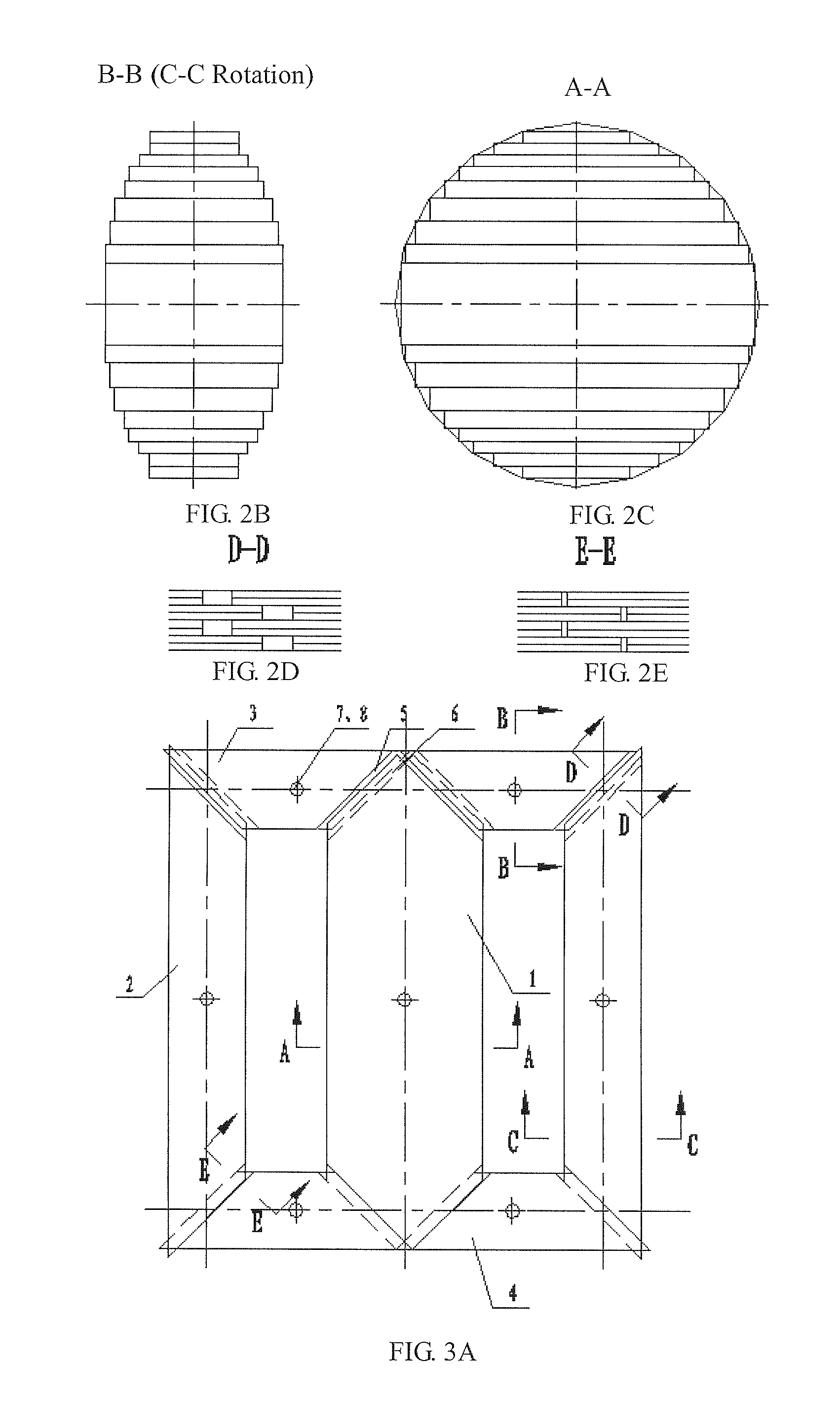
[0043]Referring to FIGS. 3A to 3E of the drawings, the difference from the exemplary embodiment 1 is that the iron core unit is a single-phase three columns unit which includes one main column 1, two side columns 2, two upper yokes 3, two lower yokes 4, wherein the number of joint portions is 6, all of which employed the enlarged joint portions. Still, one set of laminate units includes two laminate units, the first level connecting joint portion 5 and the second level connecting joint portion 6 are alternately positioned. The laminate units are mounted into position by employing positioning hole 7 and screw unit 8.

[0044]According to the different requirements of different converter transformer, the laminate units of different levels can be place alternately with 1 to 6 level of laminate units, the mounting of laminate units can also employ other method such as boding with bonding element or tying with strap element.

[0045]One skilled in the art will understand that the embodiment of...


PUM

PropertyMeasurementUnit
widthaaaaaaaaaa
widthaaaaaaaaaa
heightaaaaaaaaaa

Abstract

A method for achieving converter transformer for suppressing DC bias magnet comprises increasing the seaming width of the transformer core lamination, which comprises in detail calculating the width and the height of each stage of lamination according to the reserved seaming width of the lamination, the sectional area of the core, the space between columns, and the height of the window, shearing the lamination based on the width and the height of the lamination obtained by calculating, overlapping two pieces of laminations into one piece of lamination according to the order of stages, placing them on the core frame alternately by stages, and after overlapping all the laminations, fastening each stage of lamination.

Description

BACKGROUND OF THE PRESENT INVENTION [0001]1. Field of Invention[0002]The present invention relates to a manufacture method of a transformer, and more particularly to a converter transformer with DC magnetic bias inhibition arrangement which is applicable for capacitance of different values.[0003]2. Description of Related Arts[0004]DC grid and geomagnetic variation are factors which increase a neutral ground point of a transformer, causing a DC bias current flowing into a coil of the transformer through the neutral and result in half-cycle saturation of magnetizing current of the transformer.[0005]In the absence of DC current in a coil assembly of a transformer, no load current works in the linear segment of the iron-core magnetization curve φ (t). At this point, the magnetizing current basically is a sine wave or approximately a sine wave which is symmetrical in shape, as shown by the solid line in FIG. 1(c). Under the influence of DC magnetic bias, which is shown in the broken line...

Claims


Application Information

Patent Timeline
Patent Type & Authority Applications(United States)
IPC IPC(8): H01F41/02
CPCY10T29/49078H01F41/0233
Inventor WANG, JIANLI, GUIPINGSUN, YONGMA, ZHIKAI
Owner TBEA SHENYANG TRANSFORMER GRP CO LTD
Why Eureka
Try Eureka