Bias-free regularization for spectral phase-unwrapping in differential phase contrast imaging

a technology of differential phase contrast and bias-free regularization, which is applied in image generation, image enhancement, instruments, etc., can solve the problems of only a limited angular range of interferometer, ambiguous phase shift data obtained via interferometer, and visible artifacts, so as to improve accuracy

Active Publication Date: 2018-07-31
KONINKLJIJKE PHILIPS NV
View PDF8 Cites 0 Cited by
  • Summary
  • Abstract
  • Description
  • Claims
  • Application Information

AI Technical Summary

Benefits of technology

[0022]The proposed methods allow avoiding or at least mitigating a bias effect introduced by the presence of the regularization term. The regularizer or regularization is likewise a real valued function that is usually solely a function of the elements in the domain of the objective function. It allows the enforcement of the desirable properties, for instance smoothness or “smallness” of the critical points to be searched for. It has been observed that if the objective function has multiple local minima (that is, the objective function is neither convex nor concave), the regularization term exerts a bias so as to shift the global minimum of the objective function into a correct range of the domain. This is desirable but the objective function also introduces an undesirable bias on the local extrema of the objective function towards said range (eg, small absolute values). As the unwrapped phase data sought for are among those local extrema, this bias carries through to the output of many phase unwrapping algorithms that are based on regularized optimization.
[0023]To overcome this bias effect, two alternative methods are proposed herein. According to one method, it is first the objective function without the regularization that is searched and then the result is applied to the regularized function. In the alternative embodiment, first the regularized function is searched and then the results are applied to the un-regularized objective function. In other words the sequence of the searching steps is reversed. In both methods the output (that is, the un-wrapped phase shift data) are ultimately points of the un-regularized objective function. In other words the critical points of the regularized objective function are not as such returned as un-wrapped phase shift data. Rather the critical points of the regularized objective function are used as a guiding means to select from the critical points of the un-regularized objective function. In this way, the bias in the searching step caused by the presence of the regularization term can be avoided or at least mitigated and yet one is still able to take account of the regularization requirements. In yet other words, the method allows striking a balance between observing the need to have regularization and to avoid or mitigate the bias so caused by said regularization terms.

Problems solved by technology

Unfortunately, the phase shift data obtained via the interferometer may be ambiguous.
This is because the interferometer has only a limited angular range.
Phase wrapping is undesirable because it may cause visible artifacts in the phase contrast images.
It has been found however, that the accuracy of the un-wrapped phase data obtainable by existing algorithms is occasionally inaccurate.

Method used


Image

  • Bias-free regularization for spectral phase-unwrapping in differential phase contrast imaging
  • Bias-free regularization for spectral phase-unwrapping in differential phase contrast imaging
  • Bias-free regularization for spectral phase-unwrapping in differential phase contrast imaging

Examples


Embodiment Construction

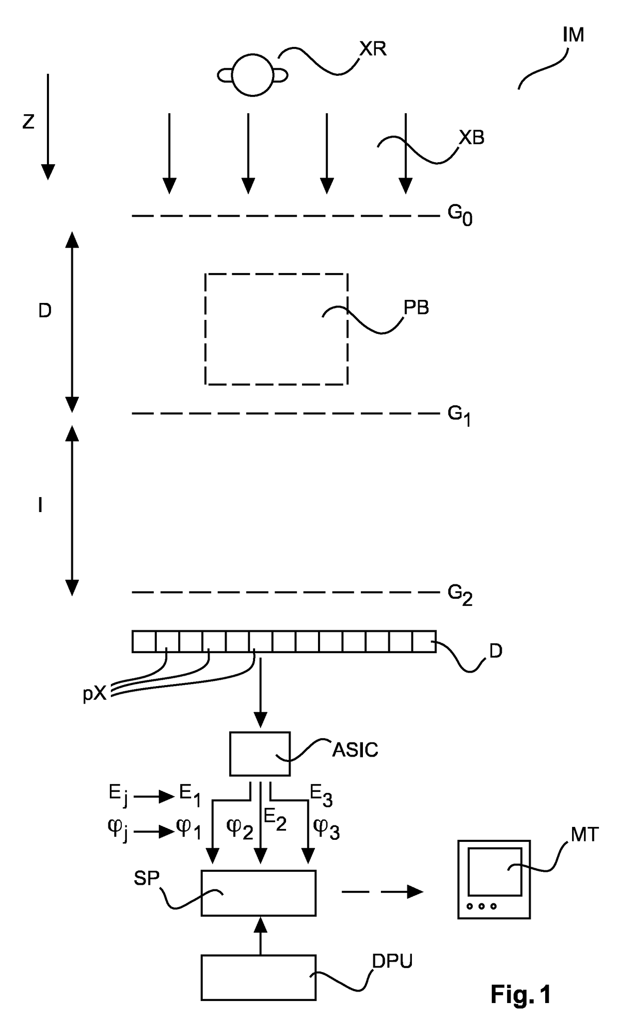
[0036]FIG. 1 shows basic components of an imaging system IM with phase contrast imaging capabilities, in particular differential phase contrast imaging (DPCI). There is an X-ray source XR for generating X-ray radiation waves XB that, after passage through an examination region, are detectable by detector pixels px of a detector D. The phase contrast imaging capability is achieved by an interferometer arranged between the X-ray source XR and the radiation sensitive detector D.

[0037]The interferometer (which in one unlimiting embodiment is of the Talbot type or of the Talbot-Lau type) includes two G1, G2 (Talbot type) or more, preferably, three gratings G0, G1 and G2 (Talbot-Lau type). The first attenuation grating G0 at the X-ray source side has a period p0 to match and cause spatial coherence of the X-ray radiation wave front emitted at the X-ray source XR.

[0038]An absorption grating G1 (having period p1) is placed at distance D from the X-ray source and causes an interference patte...


PUM


Abstract

Methods and related apparatus (SP) to correct phase shift image data for phase wrapping artifacts. The data is detected at a detector (D) of an imaging system (IM) including interferometric equipment (G0, G1, G2). In a phase unwrapping method that involves optimizing an objective function with regularization, a two-sage approach is proposed. The measured data is processed in one stage with regularization and in the other stage without regularization. This allows improving the accuracy of the corrected (phase unwrapped) phase shift data because an undesirable bias caused by the regularization can be avoided.

Description

CROSS REFERENCE TO RELATED APPLICATIONS[0001]This application is the U.S. National Phase application under 35 U.S.C. § 371 of International Application No. PCT / EP2015 / 058566, filed Apr. 21, 2015, published as WO 2015 / 185259 on Dec. 10, 2015, which claims the benefit of European Patent Application Number 14170740.6 filed Jun. 2, 2014. These applications are hereby incorporated by reference herein.FIELD OF THE INVENTION[0002]The invention relates to methods for processing measured phase shift data, to signal processing apparatuses, to computer program elements and to computer readable media.BACKGROUND OF THE INVENTION[0003]In a range of technical applications including the medical field phase contrast imaging has been recognized as superior to solely absorption based imaging techniques for its excellent soft tissue contrast. In some applications phase contrast imaging requires an interferometer mounted in an imaging apparatus. The interferometric set up allows extracting a certain pha...

Claims


Application Information

Patent Timeline
Patent Type & Authority Patents(United States)
IPC IPC(8): G06K9/00G06T7/00G06K9/46
CPCG06T7/0012G06K9/4671G06T2207/10116G06T11/005A61B6/484G06T2211/408
Inventor KOEHLER, THOMASPROKSA, ROLAND
Owner KONINKLJIJKE PHILIPS NV
Why Eureka
Try Eureka