
Cleaning and charging station

a charging station and charging circuit technology, applied in the field of cleaning and charging stations, can solve the problems of malfunction of the station and the components of the station, and achieve the effects of avoiding or minimizing the risk of electrical components malfunction, avoiding or minimizing the risk of circuit boards being exposed to cleaning liquid

Active Publication Date: 2021-10-19
BRAUN GMBH
View PDF10 Cites 2 Cited by
  • Summary
  • Abstract
  • Description
  • Claims
  • Application Information

AI Technical Summary

Benefits of technology

[0005]It is an object of the present disclosure to provide a cleaning and charging station minimizing the risk of malfunction of electrical components due to exposure to cleaning liquid.
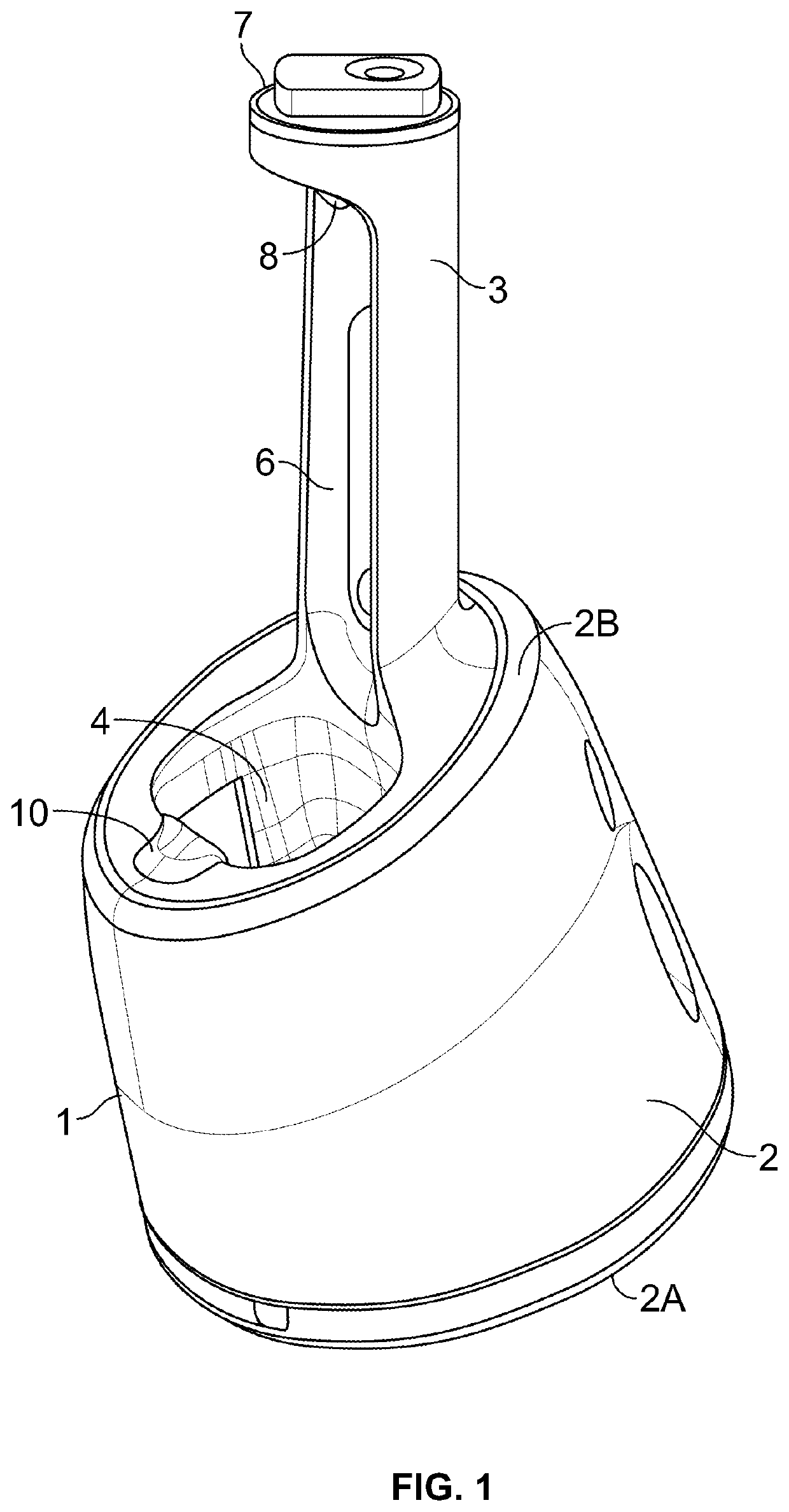
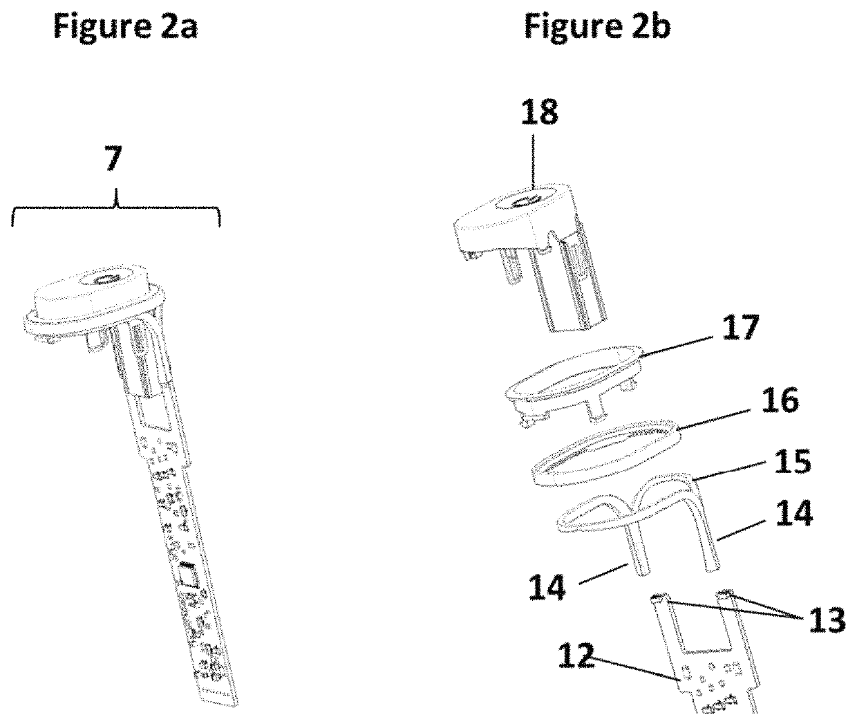
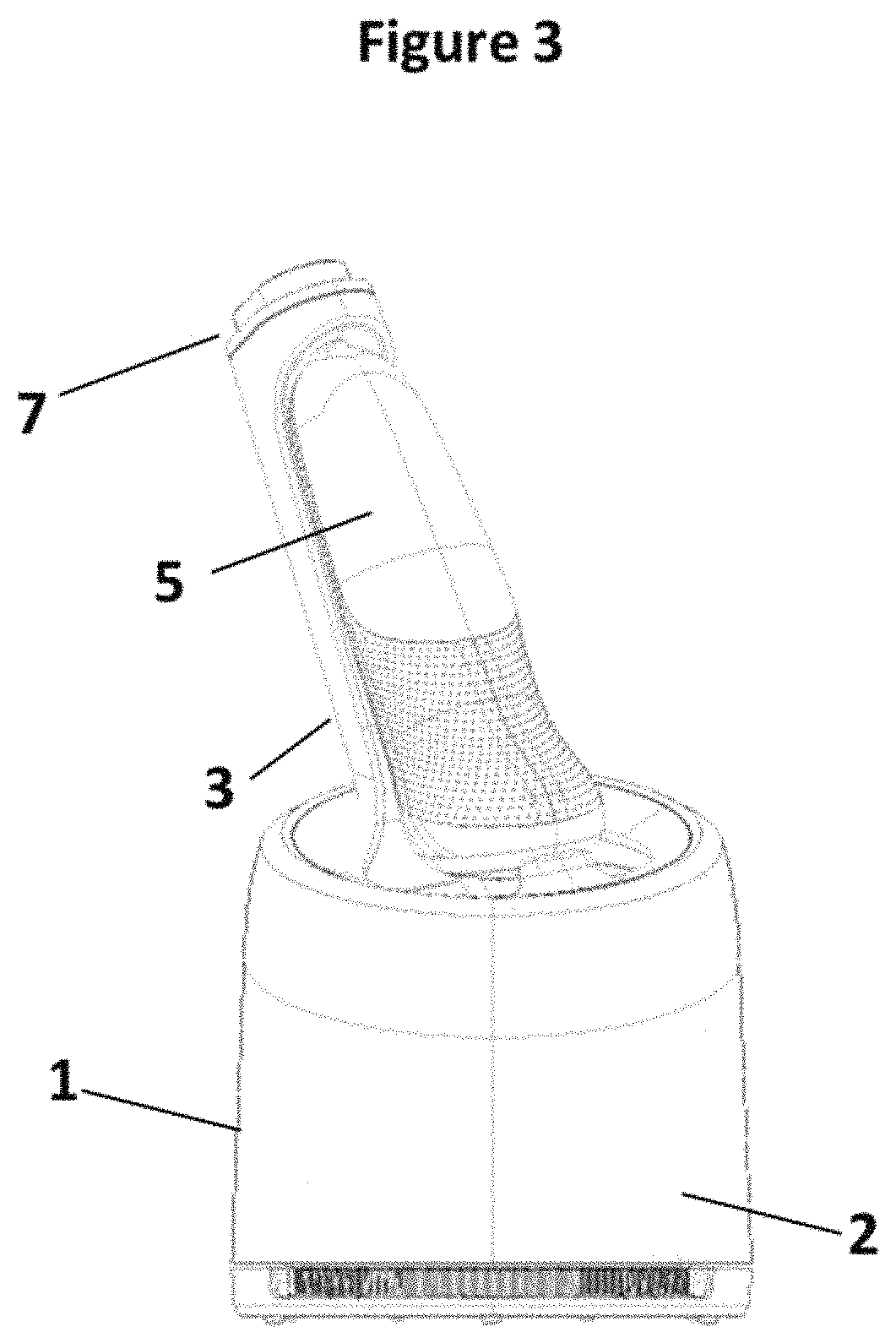
[0006]This object is solved by a cleaning and charging station as defined in claim 1. In accordance with one aspect there is provided a cleaning and charging station comprising a housing with a base portion and a gallows structure extending from the base portion. The base portion comprises a cleaning chamber for at least partially receiving the electrically driven device and the gallows structure comprises a charging terminal for charging the electrically driven device. Further, the circuit board is located in the gallows structure at a position spaced from the cleaning chamber. Arranging the circuit board at a position remote from the cleaning chamber, the risk of exposing the circuit board to the cleaning liquid is minimized. The location of the circuit board in the gallows structure has the further benefit that the circuit board is at a position in the vicinity of components connected and / or coupled to the circuit board, thereby potentially avoiding or at least reducing cables or wiring. For example, a lighting unit, a display unit, a selector for choosing an operation mode or status of the station and / or a start button may be provided directly on the circuit board or at least in the vicinity of the circuit board.

Problems solved by technology

There is a risk that the cleaning liquid comes in contact with the control unit, which may result in a malfunction of the station.
Several electrical components are arranged in the vicinity of the cleaning chamber, such that there is a risk of malfunction of these components if they come in contact with the cleaning liquid.

Method used


Image

  • Cleaning and charging station
  • Cleaning and charging station
  • Cleaning and charging station

Examples


Embodiment Construction

[0014]Before describing advantageous embodiments of the invention related to the embodiments depicted in FIGS. 1 to 5, different aspects of the invention are described more in detail. These aspects disclose further features, advantages and possibilities of use of the present invention that might be combined in any useful combination. All features described and / or shown in the drawings are subject matter of the invention, irrespective of the grouping of the features in the claims and / or their back references.

[0015]According to an aspect of the present disclosure, the base portion 2 comprises a support face 2A located on a vertically lower side during use of the station and a collar 2B located opposite the support face. The gallows structure may extend from the collar of the base portion in a direction facing away from the support face. In other words, the gallows structure with the circuit board are located vertically above the base portion with the cleaning chamber during use of the...


PUM


Abstract

The invention relates to a cleaning and charging station for an electrically driven device. The station comprising an outer housing with a base portion and a gallows structure extending from the base portion. The base portion comprises a cleaning chamber for at least partially receiving the electrically driven device and the gallows structure comprises a charging terminal for charging the electrically driven device. The station further comprises a circuit board mounted within the housing and connected to the charging terminal. The circuit board is located in the gallows structure at a position spaced from the cleaning chamber.

Description

FIELD OF THE INVENTION[0001]The present invention is concerned with a cleaning and charging station for an electrically driven device, for example an electric hair removal device, such as a dry shaver, an electric toothbrush or an electric skin treatment device.BACKGROUND OF THE INVENTION[0002]Generally, there are at least two types of electric shaver cleaning and battery loading / charging stations are more available at the market and both differ in the way how the shaver is electrically contacted with the station. In a first way the shaver is provided with electrical contacting pins at the lateral housing side which is often the opposite side of the on / off button housing side and the clean and charging station is provided with shaver electrical contacts in an area adjacent to the cleaning chamber. In a second way the shaver electrical socket provided often at the end of the housing opposite to the other end with the cutting units is used as electrical contacting means to contact wit...

Claims


Application Information

Patent Timeline
Patent Type & Authority Patents(United States)
IPC IPC(8): B26B19/38A45D27/46F21V3/02H02J7/00F21Y115/10
CPCB26B19/388A45D27/46B26B19/3826B26B19/3833F21V3/02H02J7/0044H02J7/0047F21Y2115/10A45D27/00
Inventor STEGMANN, WOLFGANGSIKORA, BERNHARDKRAUSS, JOACHIMLUDAESCHER, UWE
Owner BRAUN GMBH
Learn More