Eureka AIR delivers breakthrough ideas for toughest innovation challenges, trusted by R&D personnel around the world.

Fragrance producing lighting device

a lighting device and fragrance technology, applied in the direction of free standing, steam generation using steam absorption, combustion air/fuel air treatment, etc., can solve the problems of affecting the display of lighting from the device, affecting the safety of persons and pets, and affecting the appearance of the devi

Inactive Publication Date: 2012-04-19
SKY RICH STAR LTD
View PDF30 Cites 117 Cited by
  • Summary
  • Abstract
  • Description
  • Claims
  • Application Information

AI Technical Summary

Benefits of technology

[0006]Another drawback to such prior device configurations is that because the heat source needed to melt the fragrance-producing wax or other substance also acts as a light emitting element, said light emitting element is required to be located in very close proximity to the fragrance producing substance so as to sufficiently warm said substance. This requirement that the light / heating source be in close proximity to the fragrance producing substance severely limits available design configurations of such devices, often leading to design compromises that results in less than optimal displays of lighting from the device.

Problems solved by technology

One drawback of the foregoing prior device configuration is that it generally requires the aforementioned tray containing hot wax to be located at the highest point of the device.
Such a configuration can potentially be dangerous to persons and pets and damaging to property if the device or an object on which the device rests is bumped forcefully enough such that the tray is partially or completely dislodged, allowing hot wax to be spilt out of the tray.
Another drawback to such prior device configurations is that because the heat source needed to melt the fragrance-producing wax or other substance also acts as a light emitting element, said light emitting element is required to be located in very close proximity to the fragrance producing substance so as to sufficiently warm said substance.
This requirement that the light / heating source be in close proximity to the fragrance producing substance severely limits available design configurations of such devices, often leading to design compromises that results in less than optimal displays of lighting from the device.
Another drawback of such prior device configurations utilizing wax type substances, and perhaps one of the least desirable aspects of such devices, is the high level of maintenance required of users of such devices.

Method used


Image

  • Fragrance producing lighting device
  • Fragrance producing lighting device
  • Fragrance producing lighting device

Examples


Embodiment Construction

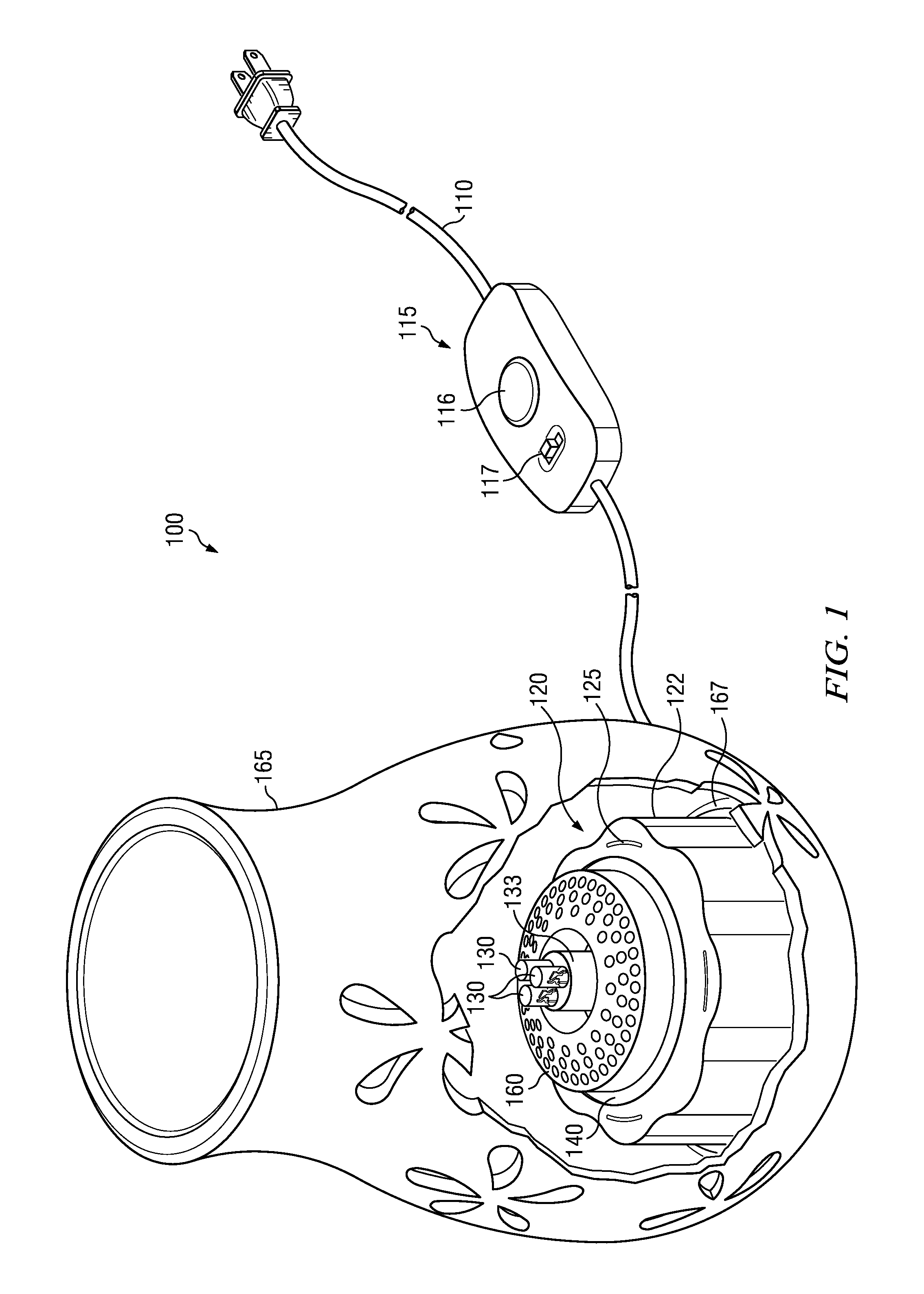
[0035]Referring to FIG. 1, a perspective view of an embodiment of the fragrance producing lighting device 100 of the present disclosure is shown. References made herein to “fragrance,”“fragrant,” or other such terms should not be interpreted as being limited to deodorizing or pleasing aromas. For example, in some embodiments, the “fragrance” may be intended as an insect repellant or chosen for medicinal purposes.

[0036]The lighting device 100 is electrically powered. In the illustrated embodiment, electrical power can be received via a wired connecting cord 110 suitable for providing for connection of the device to an A / C power source such as a common residential 110 volt or 220 volt outlet (not shown). Although the illustrated embodiment of the device 100 is configured to be connected to an A / C power source, it is contemplated that alternative embodiments may be powered by additional and / or alternative means, for example battery power sources capable of providing the necessary power...


PUM

PropertyMeasurementUnit
timeaaaaaaaaaa
timeaaaaaaaaaa
timeaaaaaaaaaa

Abstract

A light and fragrance producing device includes an electrically powered light source and a separate electrically powered heating element. The device also includes a fragrance disk that can emit fragrances when heated by the heating element. The fragrance disk also can be configured to remain solid while heated by the heating element rather than melting or evaporating. The device can also include a decorative outer housing that can be interchangeable.

Description

RELATED APPLICATIONS[0001]This is a continuation-in-part application of U.S. patent application Ser. No. 13 / 171,730, filed Jun. 29, 2011, titled “FRAGRANCE PRODUCING LIGHTING DEVICE,” which is hereby incorporated herein by reference. This application also claims the benefit of U.S. Provisional Patent Application No. 61 / 434,185, filed Jan. 19, 2011, titled “FLAMELESS CANDLE WARMERS AND FRAGRANCE DISKS,” which is hereby incorporated herein by reference.BACKGROUND[0002]1. Technical Field[0003]The present disclosure relates generally to electrically-powered lighting devices and, in particular, to an electric lighting device capable of dispersing fragrances through the use of a polymeric disk impregnated with said fragrances that are released into the air surrounding the device during operation.[0004]2. Related Art[0005]Various configurations of electrically-powered fragrance producing lighting devices are known. Typically, such prior devices use various heat sources, such as a tea light...

Claims


Application Information

Patent Timeline
Patent Type & Authority Applications(United States)
IPC IPC(8): A61L9/015
CPCA61L9/015A61L9/03F21V33/0004A61L2209/12F21S6/001A61L9/14
Inventor BROWDER, JOHNKOWALEC, MATTHEWRUSHING, ALANMOODY, BRETT
Owner SKY RICH STAR LTD
Why Eureka
Eureka Blog
Learn More