Window trim having integrated window box gasket

a window box and window trim technology, applied in the direction of joints, tightening/covering, construction, etc., can solve the problems of labor intensive and unsightly appearance, and achieve the effect of saving the installer a significant amount of tim

Inactive Publication Date: 2012-04-26
CASHMAN DANIEL
View PDF17 Cites 2 Cited by
  • Summary
  • Abstract
  • Description
  • Claims
  • Application Information

AI Technical Summary

Benefits of technology

[0012]Conventionally, the inside perimeter is a simple board edge and the window box must be caulke...

Problems solved by technology

This is labor inten...

Method used


Image

  • Window trim having integrated window box gasket
  • Window trim having integrated window box gasket
  • Window trim having integrated window box gasket

Examples


Embodiment Construction

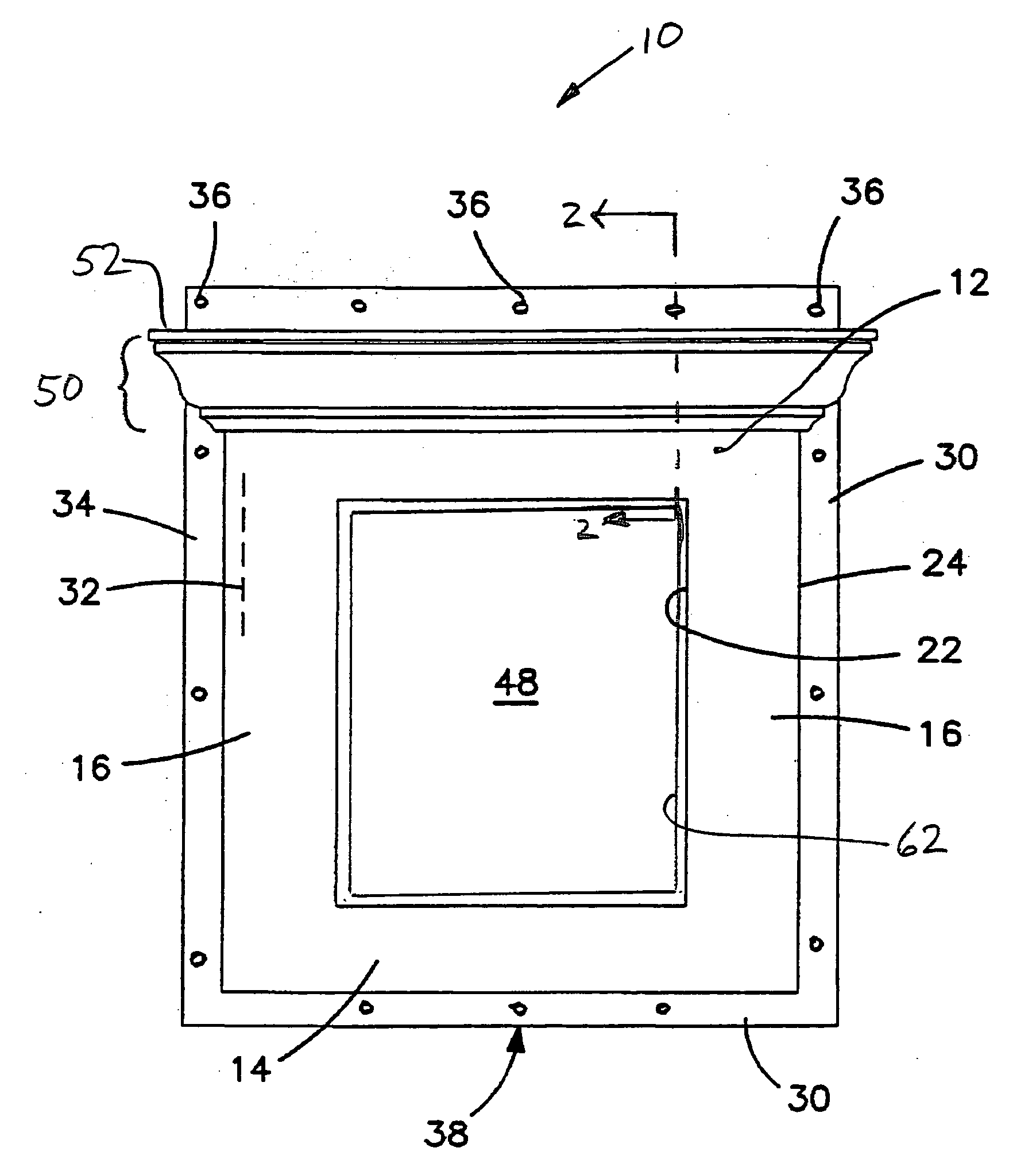
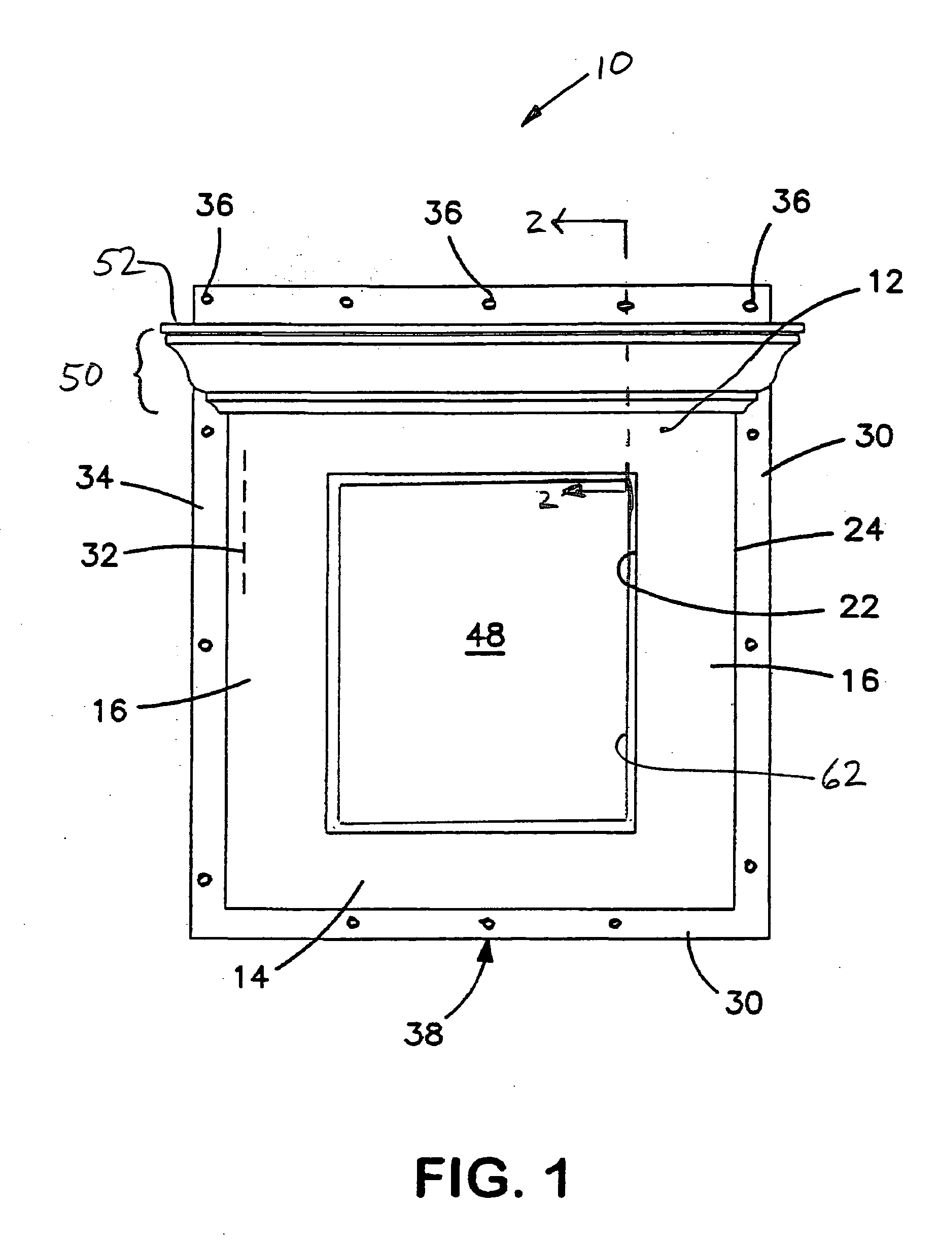
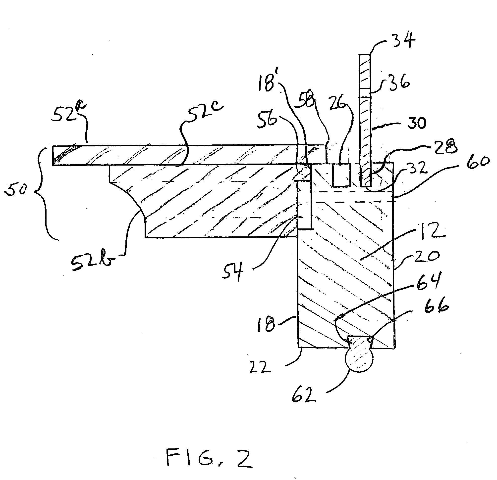
[0021]The first embodiment will be described with reference to FIGS. 1-4, which show a prefabricated window frame 10, having top element 12, a bottom element 14 and side elements 16 connected together to define a rectangular frame, each element having front 18 and back faces, and inner 22 and outer 24 edges. At least the side elements 16, but preferably also the top and bottom elements 12, 14 have a channel 28 in which mounting strips 30 have been press fit. Optionally, the edges can also include another channel indicated at 26 in FIG. 2, to facilitate installation of vinyl or aluminum siding against the frame as described in U.S. Publication 2009 / 0277110. The inner edge 32 of the mounting strip 30 is retained well within the edge 22 of the frame, and the outer edge 34 of the strip extends outside the perimeter of the frame, where mounting holes 36 are provided in the strip.

[0022]Whether prefabricated as an entire unit or assembled on site as such unit, the frame with strips and / or ...


PUM


Abstract

A window or other trim frame having an opening defined by inside edges of connected frame elements for surrounding a window box or the like having outside edges with a small gap, wherein one of the edges carries a pre-installed gasket for passively sealing the gap and thereby avoiding the need to caulk the gap.

Description

RELATED APPLICATION[0001]This application claims the benefit under 35 U.S.C. §120, of U.S. patent application Ser. No. 12 / 152,112 filed May 12, 2008 and published as US 2009 / 0277110 on Nov. 12, 2009, for “Window Frame With Installation Flange”, and U.S. patent application Ser. No. 12 / 383,985 filed Mar. 31, 2009 and published as US 2010 / 0242384 on Sep. 30, 2010 for “Rapid Install Mantle”, the entire disclosures of which are hereby incorporated by reference.BACKGROUND[0002]The present invention relates to building construction and in particular to the installation of trim on the building exterior.[0003]Window trim units surrounding a window box in a building wall penetration are shown and described in U.S. Pat. Pub. 2009 / 0277110. Conventionally, the window box is attached to the building exterior wall around the penetration and defines an outer perimeter for receiving window trim (e.g., window frame). The window box and window frame are structurally attached to the building wall aroun...

Claims


Application Information

Patent Timeline
IPC IPC(8): E06B1/36
CPCE06B1/34E06B2001/628E06B1/62
Inventor CASHMAN, DANIEL
Owner CASHMAN DANIEL
Why Eureka
Try Eureka