Round Baler For Baling Crop Residue

a crop residue and baler technology, applied in baling, agriculture tools and machines, agriculture, etc., can solve the problems of time-consuming and extensive changes

Active Publication Date: 2012-04-26
DEERE & CO
View PDF16 Cites 48 Cited by
  • Summary
  • Abstract
  • Description
  • Claims
  • Application Information

AI Technical Summary

Problems solved by technology

These modifications require extensive changes that are time consuming to make, including removal of the existing crop pickup for picking up windrowed crop.

Method used


Image

  • Round Baler For Baling Crop Residue
  • Round Baler For Baling Crop Residue
  • Round Baler For Baling Crop Residue

Examples


Embodiment Construction

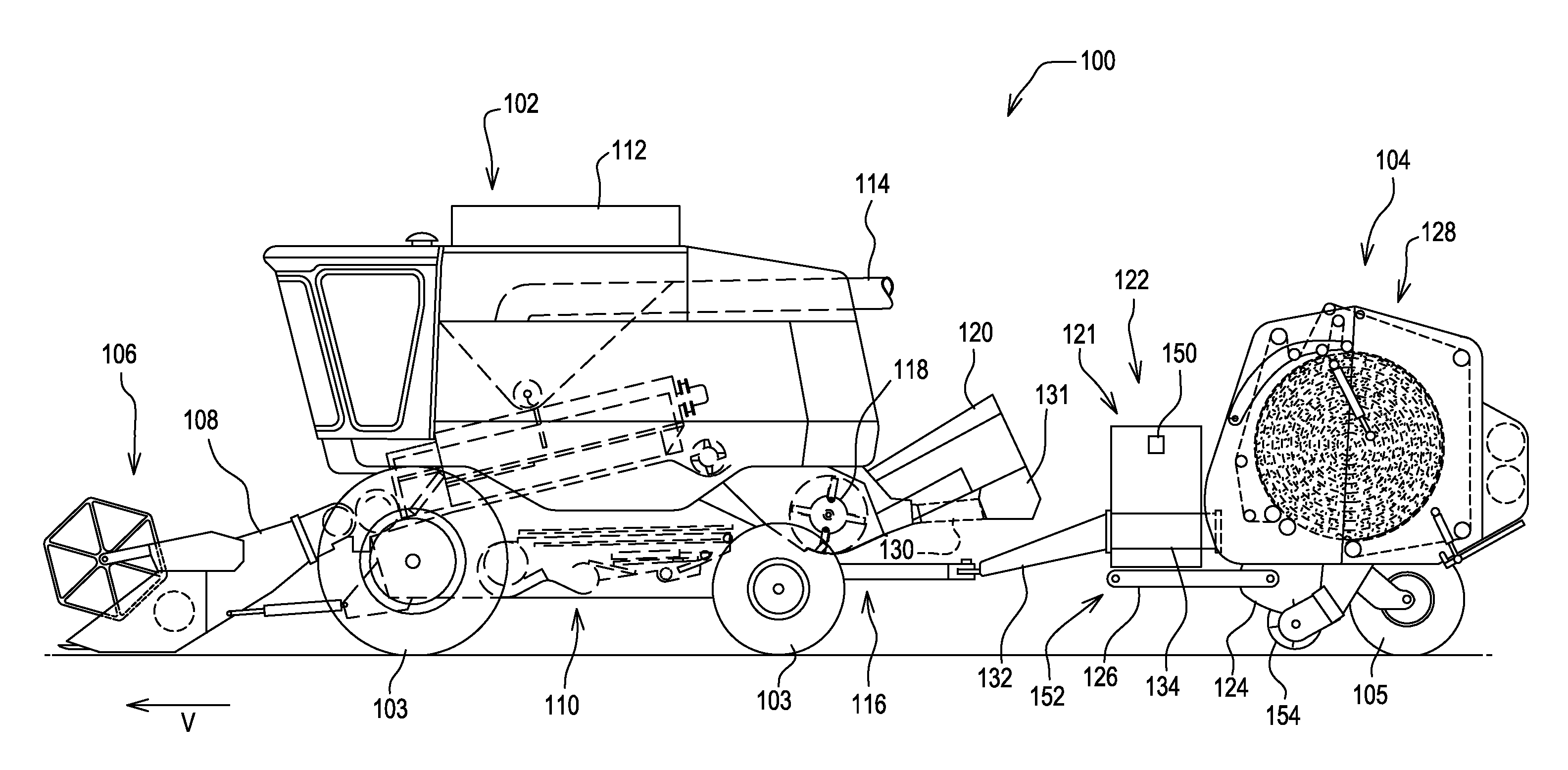
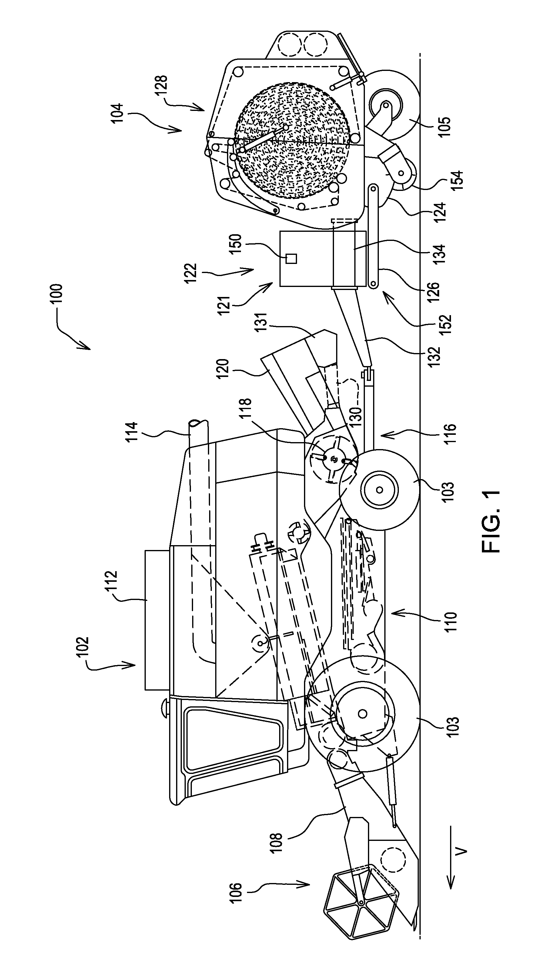
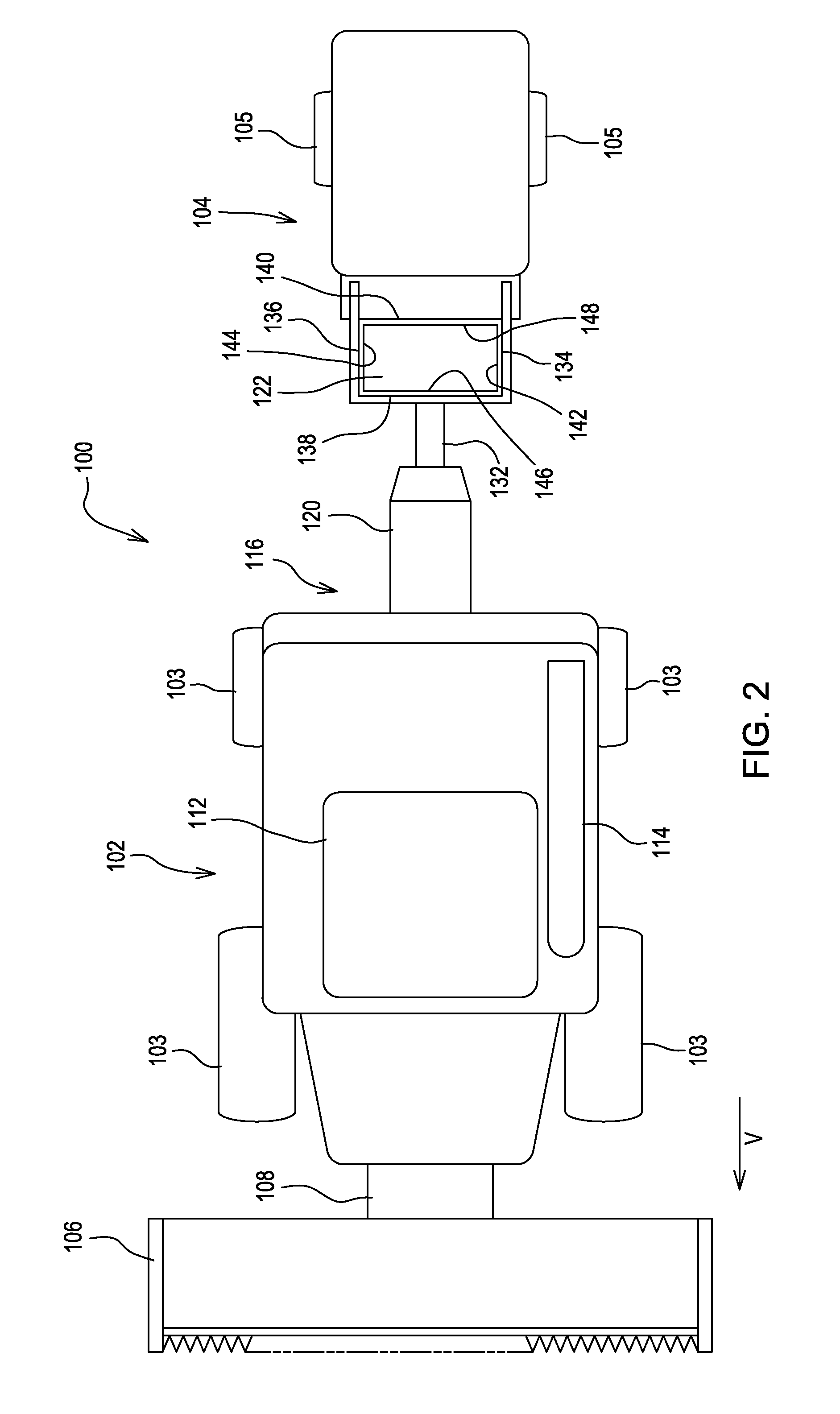
[0019]Referring to FIGS. 1 and 2, a harvesting machine 100 comprises an agricultural combine 102, supported on wheels103. and towing a baler 104. The agricultural combine 102 has a header 106 mounted on the front that extends laterally with respect to the direction of travel “V”. The header 106 separates portions of the crop plants from the ground and conveys them to a central portion of the header 106. The header 106 is supported on a feederhouse 108 that has an internal conveyor to convey cut crop material from the header 106 to the agricultural combine 102.

[0020]Once inside the agricultural combine 102, the cut crop material is processed by a threshing, separating, and cleaning section 110 that threshes, separates and cleans the crop; an elevator (not shown) receives the grain and deposits it in a grain tank 112. The grain is subsequently unloaded by an unloading conveyor 114 into a cart or truck located alongside the agricultural combine 102. Crop material other than grain (MOG)...


PUM


Abstract

A method of converting a conventional round baler to a round baler with an accumulator chamber is disclosed.

Description

RELATED APPLICATIONS[0001]This application claims priority to U.S. Provisional Patent Application No. 61 / 406,574, filed 2010-10-25, which is incorporated by reference herein for all that it teaches.FIELD OF THE INVENTION[0002]This invention relates to agricultural machines. In particular at this invention relates to harvesting machines.BACKGROUND OF THE INVENTION[0003]Agricultural machines called balers are provided to gather cut crop material and secure it together in bundles of cut crop material called “bales”. In one arrangement, plants are severed in the field and laid down in windrows to dry. These windrows are later lifted off the field by balers and secured into bales. In another arrangement, the crop plants are severed from the ground and are conveyed into a baler, sometimes conveyed directly, sometimes conveyed after some preliminary processing, such as separating grains from the rest of the plant.[0004]It has been proposed recently to attach round and square balers to comb...

Claims


Application Information

Patent Timeline
Patent Type & Authority Applications(United States)
IPC IPC(8): A01D75/00
CPCA01F15/0833A01D43/006A01F15/106
Inventor CHANEY, MARK M.PATTON, STEPHEN MICHAEL
Owner DEERE & CO
Why Eureka
Try Eureka