Apple wedger

a wedger and apple technology, applied in the field of wedgers, can solve the problems of reducing the use of current devices, reducing the risk of cuts or injuries,

Active Publication Date: 2012-05-03
PROGRESSIVE INT
View PDF18 Cites 21 Cited by
  • Summary
  • Abstract
  • Description
  • Claims
  • Application Information

AI Technical Summary

Benefits of technology

[0008]In some examples the pusher is hingedly attached to the slicer so that it can swing away from or toward the slicer in a pivotal fashion. When pivoted

Problems solved by technology

Unfortunately, the current devices can be difficult to use because they do not readily push all the way through an apple or other food item.
This

Method used


Image

  • Apple wedger
  • Apple wedger
  • Apple wedger

Examples


Embodiment Construction

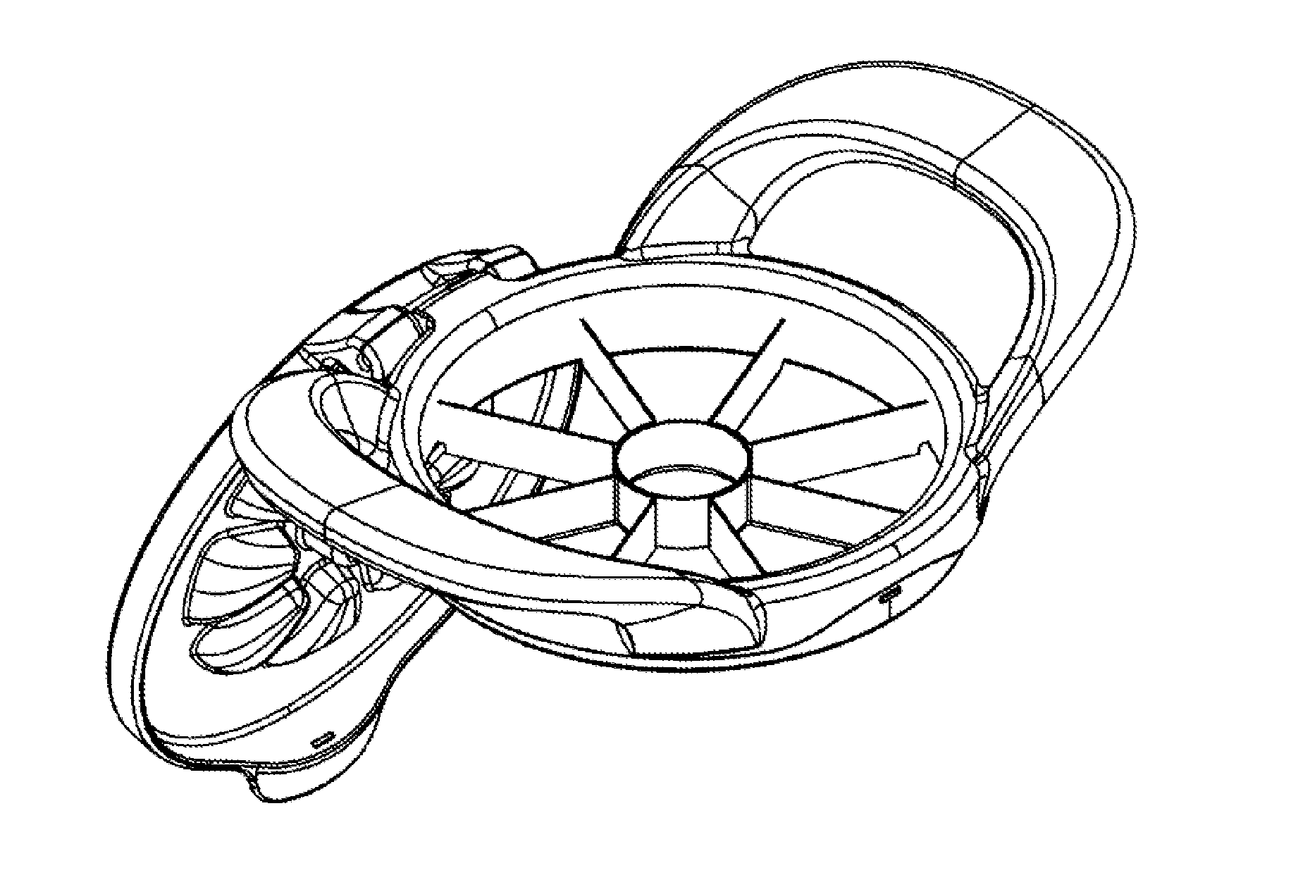
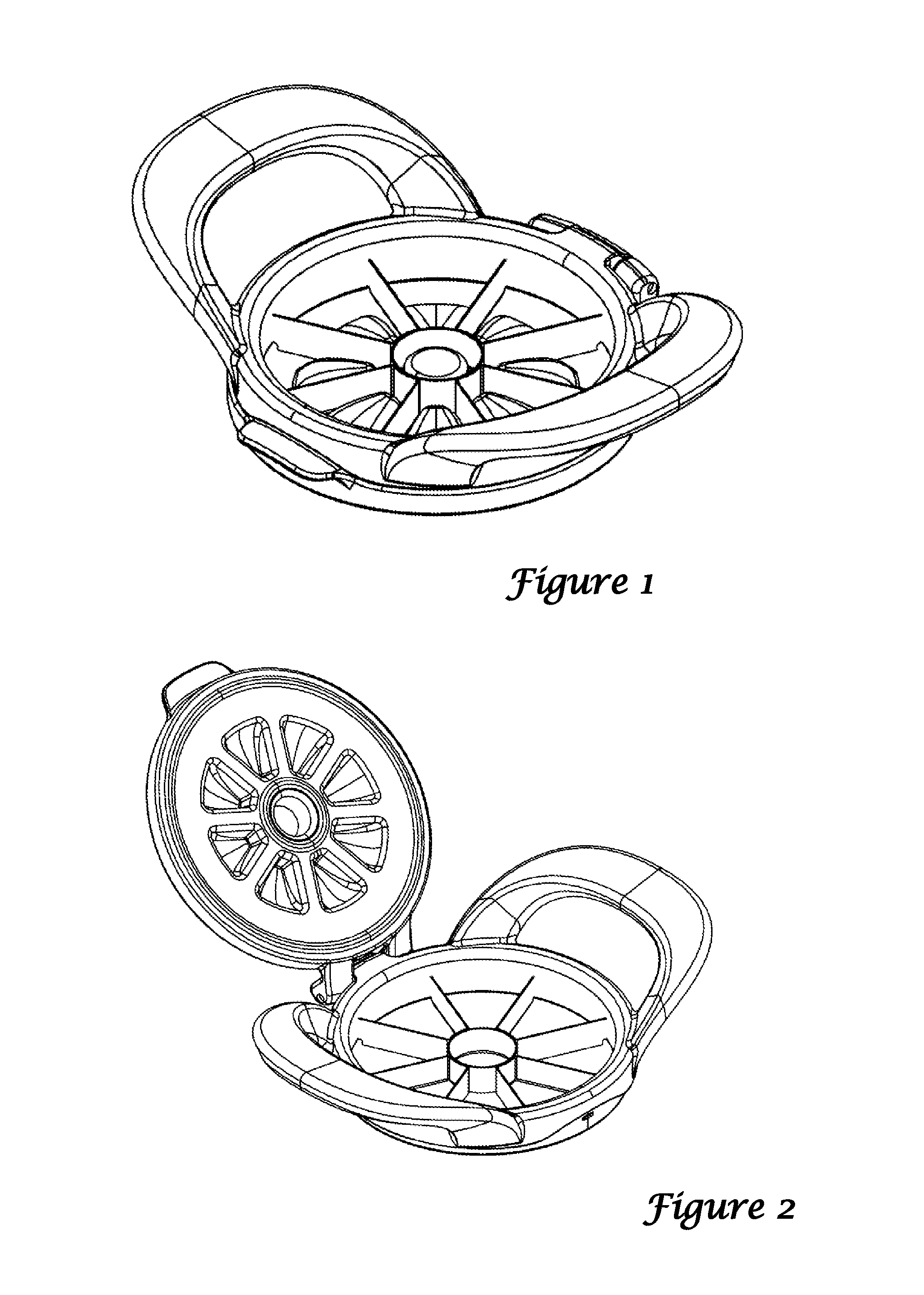
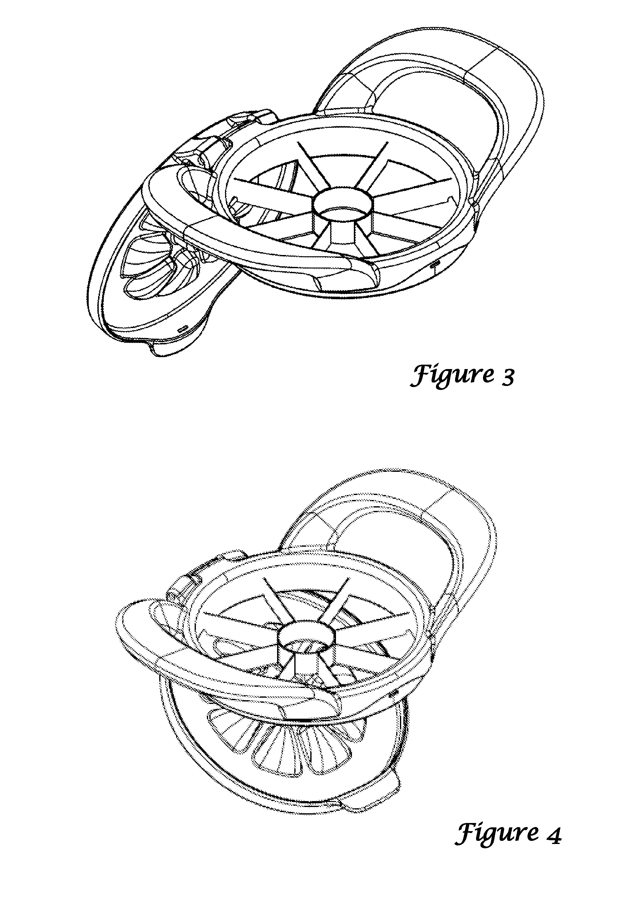
[0016]A preferred version of the apple slicer and wedger is shown in the Figures as described below. As illustrated, the wedger includes a slicer 10 and a pusher 100 pivotally secured to the slicer.

[0017]The slicer includes a peripheral frame 20 that is preferably formed in a ring or circular shape. In some alternate versions, the frame may be square or have a different shape other than circular. In a preferred example, the frame is rigid and formed from plastic, stainless steel, or other materials of sufficient strength to withstand the force imparted by urging the blades through an apple.

[0018]The blade portion of the slicer includes a central ring blade 30 and several radial blades 40 spanning the distance between the ring blade and the frame. Because the ring blade is located substantially at the center of the frame, each of the radial blades is substantially identical and divides the annular space between the frame and ring blade into equal wedge-shaped sections. In a preferred...


PUM

PropertyMeasurementUnit
Angleaaaaaaaaaa
Angleaaaaaaaaaa

Abstract

An apple wedger for cutting fruits or vegetables into wedges or other desired shapes includes a slicer and a pusher, in which the slicer has a peripheral frame and internal cutting blades. The pusher is configured to be used to push at least partially sliced food items through the gaps between cutting blades. In some versions, the pusher is pivotally attached to the slicer.

Description

PRIORITY CLAIM[0001]This application claims the benefit of prior U.S. provisional application Ser. No. 61 / 407,761 filed Oct. 28, 2010, the contents of which are hereby incorporated by reference.FIELD OF THE INVENTION[0002]This application relates to slicing devices, particularly including devices for slicing fruits and vegetables.BACKGROUND OF THE INVENTION[0003]Devices for cutting apples into sections have been available for many years. In a typical device, several radial blades are supported by a central hub blade and an outer frame. As the device is pushed downward over an apple, the central hub blade cuts the core into a central cylinder while the radial blades divide the remaining apple into several wedge-shaped sections.[0004]Unfortunately, the current devices can be difficult to use because they do not readily push all the way through an apple or other food item. The skin of an apple, for example, may provide resistance against a complete cut. This leads to users pushing agai...

Claims


Application Information

Patent Timeline
IPC IPC(8): A47J25/00B26B3/04
CPCB26D7/18B26D3/26Y10T83/04
Inventor HAUSER, LAWRENCE M.
Owner PROGRESSIVE INT
Why Eureka
Try Eureka