Speaker device

a speaker device and speaker technology, applied in the direction of transducer details, electrical transducers, record carriers, etc., can solve the problems of degrading the reproducing efficiency difficult to make thin devices, and large total height of the speaker device, and achieve the effect of high reproducing efficiency

Inactive Publication Date: 2012-05-10
PIONEER CORP +1
View PDF13 Cites 17 Cited by
  • Summary
  • Abstract
  • Description
  • Claims
  • Application Information

AI Technical Summary

Benefits of technology

[0009]One or more embodiments of the present invention provides a thin speaker device capable of emitting loud reproduced sound, achiev

Problems solved by technology

Accordingly, particularly in a speaker device adapted to a large sound volume, the total height of the speaker device inevitably becomes large.
Thus, it becomes difficult to make a thin device.
If the vibration direction of a

Method used


Image

  • Speaker device
  • Speaker device
  • Speaker device

Examples


Embodiment Construction

[0039]Hereinafter, embodiments of the present invention are described with reference to the drawings. The embodiments of the present invention include what is shown in the drawings, but are not limited to this alone. In the description hereinafter, the same symbol is applied to the same part as the part that has already been described, and thus a part of the same description may not be repeated. In embodiments of the invention, numerous specific details are set forth in order to provide a more thorough understanding of the invention. However, it will be apparent to one of ordinary skill in the art that the invention may be practiced without these specific details. In other instances, well-known features have not been described in detail to avoid obscuring the invention.

[Basic Configuration of a Speaker Device: FIG. 2]

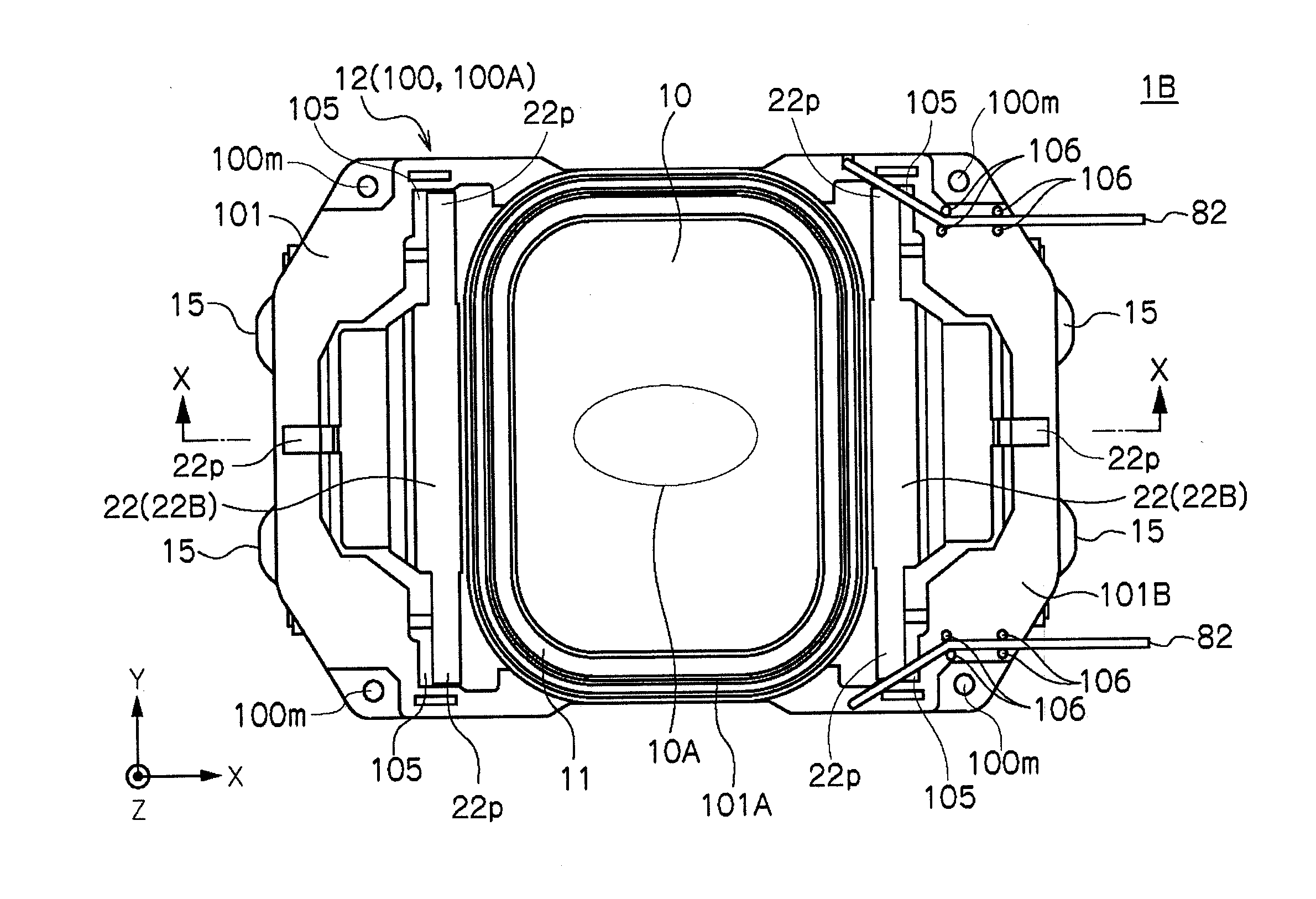
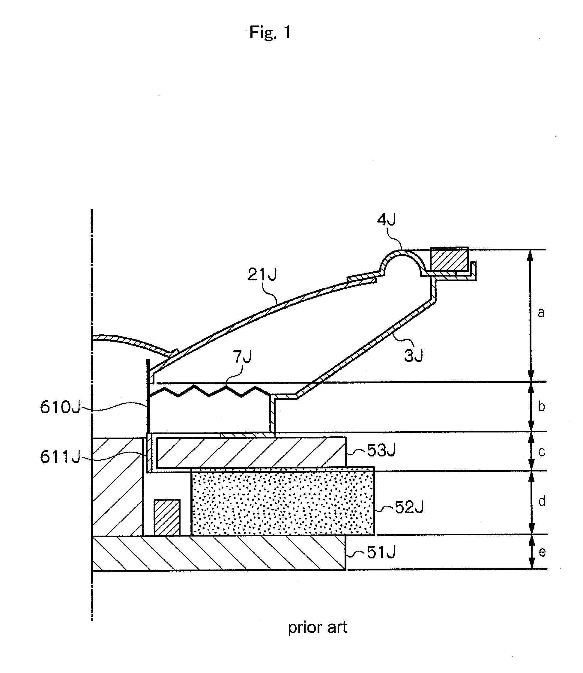
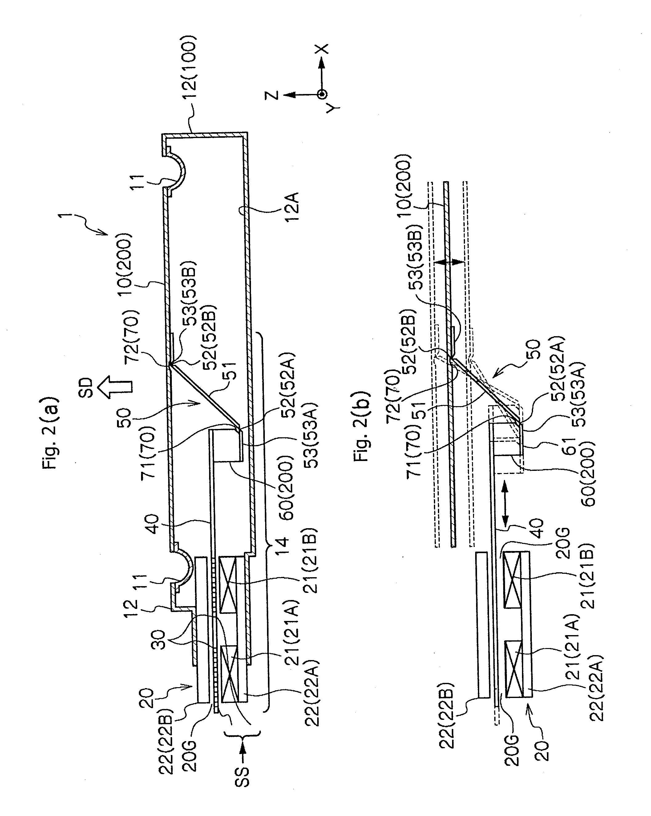
[0040]FIG. 2 is a view illustrating a basic configuration of a speaker device according to an embodiment of the present invention (FIG. 2(a) is a cross-sectional view t...


PUM

PropertyMeasurementUnit
Thicknessaaaaaaaaaa
Shapeaaaaaaaaaa
Stiffnessaaaaaaaaaa

Abstract

A speaker device has a diaphragm, a static part vibratably supporting the diaphragm in a vibration direction and a driving part applying vibration to the diaphragm in response to an audio signal. The driving part is provided at the static part. The driving part includes a magnetic circuit forming a magnetic gap in a direction different from the vibration direction of the diaphragm, a voice coil vibrating along the magnetic gap, and a vibration direction converter part direction-converting the vibration of the voice coil and transmitting the vibration to the diaphragm. The vibration direction converter part includes a link body angle-converting a link part formed between the voice coil and the diaphragm. The static part includes an outer peripheral frame part surrounding the diaphragm and a bridge part bridging the inside of the outer peripheral frame part.

Description

BACKGROUND[0001]1. Field of the Invention[0002]The present invention relates to a speaker device.[0003]2. Background Art[0004]A dynamic speaker device is known as a typical speaker device (for example, see patent literature 1). The dynamic speaker device, for example, as shown in FIG. 1, includes a frame 3J, a cone-shaped diaphragm 21J, an edge 4J through which the diaphragm 21J is supported by the frame 3J, a voice coil bobbin 610J joined to the inner periphery part of the diaphragm 21J, a damper 7J through which the voice coil bobbin 610J is supported by the frame 3J, a voice coil 611J wound around the voice coil bobbin 610J, a yoke 51J, a magnet 52J, a plate 53J, and a magnetic circuit forming a magnetic gap in which the voice coil 611J is arranged. In this speaker device, when an audio signal is inputted to the voice coil 611J, the voice coil bobbin 610J vibrates by a Lorentz force developed in the voice coil 611J in the magnetic gap and the diaphragm 21J is driven by the vibrat...

Claims


Application Information

Patent Timeline
IPC IPC(8): H04R9/06H04R31/00H04R9/04
CPCH04R9/02Y10T29/49575H04R9/047
Inventor HORIGOME, MINORUABE, YASUHISAHIKICHI, TOSHIHIRO
Owner PIONEER CORP
Why Eureka
Try Eureka