Speaker device

Inactive Publication Date: 2011-03-03
PIONEER CORP +1
View PDF13 Cites 4 Cited by
  • Summary
  • Abstract
  • Description
  • Claims
  • Application Information

AI Technical Summary

Benefits of technology

[0010]It is an object of the present invention to overcome the problems described above. More specifically, an object of the present invention is to provide a thin speaker device capable of emitting a loud sound with a comparatively simple structure, a thin speaker device with high reproducing efficiency capable of securely transmitting the vibration of the voice coil to the diaphragm and a thin speaker device capable of emitting a reproduced sound with high sound quality with a comparatively simple structure. Further, it is an object of the present invention to provide a thin speaker device in which the diaphragm vibrates substantially in the same phase with a comparatively simple structure. Further, it is an object of the present invention to provide a thin speaker device in which the diaphragm vibrates substantially in the same phase with a comparatively simple configuration. It is an object of the present invention to provide a thin speaker device while having high-quality loud sound in low frequencies with a large area diaphragm. It is an object of the present invention to prevent unwanted sounds emitted from a mounting part of a speaker, etc., which is caused by vibration of the magnetic circuit that is generated by reaction from a vibration system and transmitted to the frame. It is an object of the present invention to prevent an adverse effect on each driving part due to heat in a speaker device, which has a driving part driving a pair of diaphragms that emit sounds in both directions.

Problems solved by technology

Accordingly, particularly in a speaker device adapted to a large sound volume, the total height of the speaker device inevitably becomes large.
Thus, it becomes difficult to make a thin device.
In other words, the problem is that making a thin device and securing a loud sound are contradictory to each other.
If the vibration direction of the voice coil 611J is different from the vibration direction of the diaphragm 21J, the vibration of the voice coil 611J may not securely transmitted to the diaphragm 21J, which may cause degradation of reproducing efficiency of the speaker device.

Method used


Image

  • Speaker device
  • Speaker device
  • Speaker device

Examples


Embodiment Construction

[0028]Hereinafter, an embodiment according to the present invention is described with reference to the drawings. The embodiment according to the present invention includes what is shown in the drawings, but is not limited to this alone. In the description hereinafter, the same symbol is applied to the same part as the part that has already been described, and thus a part of the same description may not be repeated.

[Whole Configuration of Speaker Device: FIG. 2, FIG. 3]

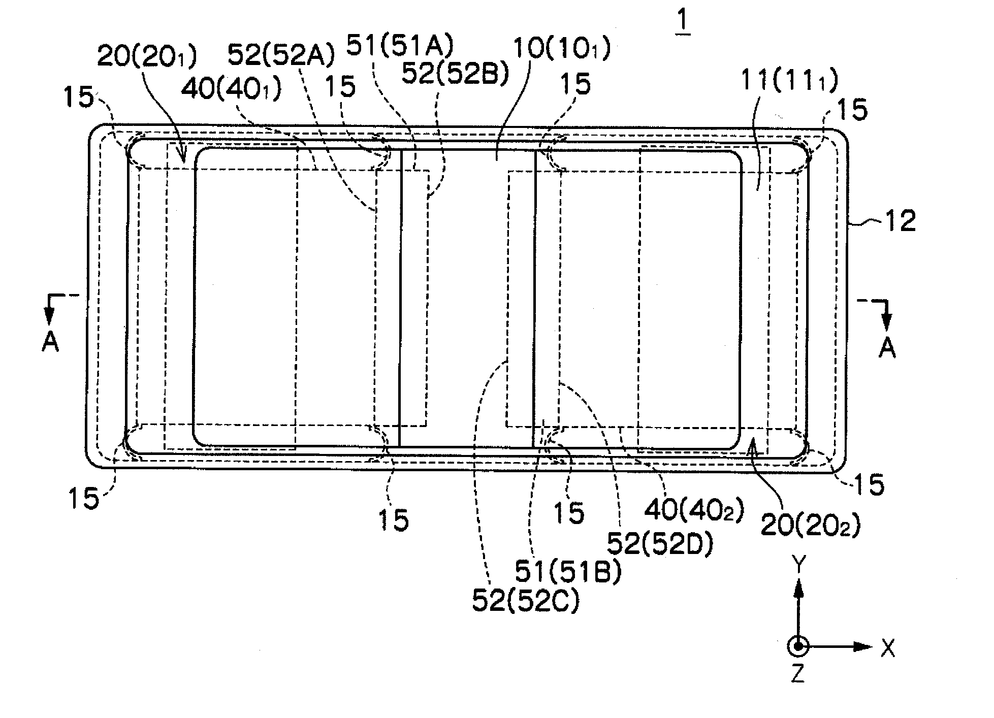
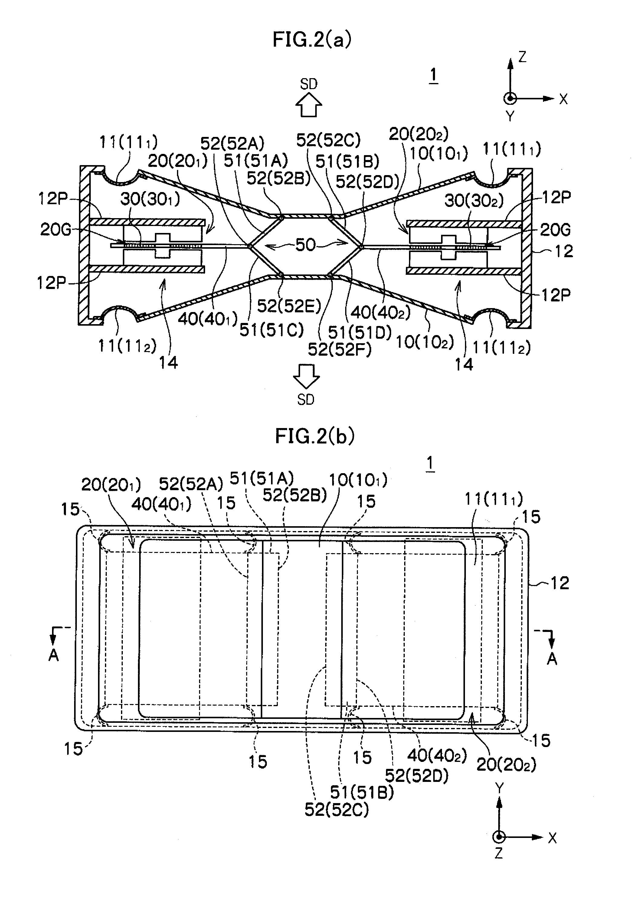
[0029]FIGS. 2 and 3 are views illustrating a whole configuration of the speaker device according to an embodiment of the present invention (FIG. 2(a) is a cross-sectional view taken along line A-A and FIG. 2(b) is a plan view). A speaker device 1 includes a pair of diaphragms 10 (101, 102) disposed opposite each other, a frame 12 vibratably supporting the outer periphery of each diaphragm 10 (101, 102) in the vibration direction and a plurality of driving parts 14 configured to support the rear surface of each diaphrag...


PUM


Abstract

A speaker device includes a pair of diaphragms disposed opposite each other, a frame configured to vibratably support an outer periphery of the diaphragms in the vibration direction, and a plurality of driving parts configured to support a rear surface of each of the diaphragms and vibrate the diaphragms in response to an audio signal. The driving parts include a pair of magnetic circuits in which a magnetic gap is formed in a direction different from the vibration direction of the diaphragms, a pair of voice coils vibratably arranged in the magnetic gap in one axis direction, vibrating so as to move toward or away from each other in response to the audio signal, and a rigid vibration direction converter part configured to convert the direction of the vibration of the voice coils and transmit the vibration to the diaphragms.

Description

FIELD OF THE INVENTION[0001]The present invention relates to a speaker device.BACKGROUND OF THE INVENTION[0002]A dynamic speaker device is known as a typical speaker device (for example, see patent literature 1). The dynamic speaker device, for example, as shown in FIG. 1, includes a frame 3J, a cone-shaped diaphragm 21J, an edge4J through which the diaphragm 21J is supported by the frame 3J, a voice coil bobbin 610J joined to the inner periphery part of the diaphragm 21J, a damper 7J through which the voice coil bobbin 610J is supported by the frame 3J, a voice coil 611J wound around the voice coil bobbin 610J, a yoke 51J, a magnet 52J, a plate 53J, and a magnetic circuit having a magnetic gap in which the voice coil 611J is arranged. In this speaker device, when an audio signal is inputted to the voice coil 611J, the voice coil bobbin 610J vibrates by a Lorentz force developed in the voice coil 611J in the magnetic gap and the diaphragm 21J is driven by the vibration.[Patent liter...

Claims


Application Information

Patent Timeline
IPC IPC(8): H04R1/00
CPCH04R9/02H04R9/06H04R9/047H04R7/02H04R9/04
Inventor OGASAWARA, YASUAKIMAEKAWA, KOJI
Owner PIONEER CORP
Why Eureka
Try Eureka