
Artificial Respirator and Operation Method Thereof

Inactive Publication Date: 2012-05-17
ULVAC KIKO +1
View PDF4 Cites 2 Cited by
  • Summary
  • Abstract
  • Description
  • Claims
  • Application Information

AI Technical Summary

Benefits of technology

[0008]In view of the above-mentioned circumstances, it is an object of the present invention to p

Problems solved by technology

Therefore, the artificial respirators cannot be easily transported for use.
Therefore, it cannot be easily transported.

Method used


Image

  • Artificial Respirator and Operation Method Thereof
  • Artificial Respirator and Operation Method Thereof
  • Artificial Respirator and Operation Method Thereof

Examples


Embodiment Construction

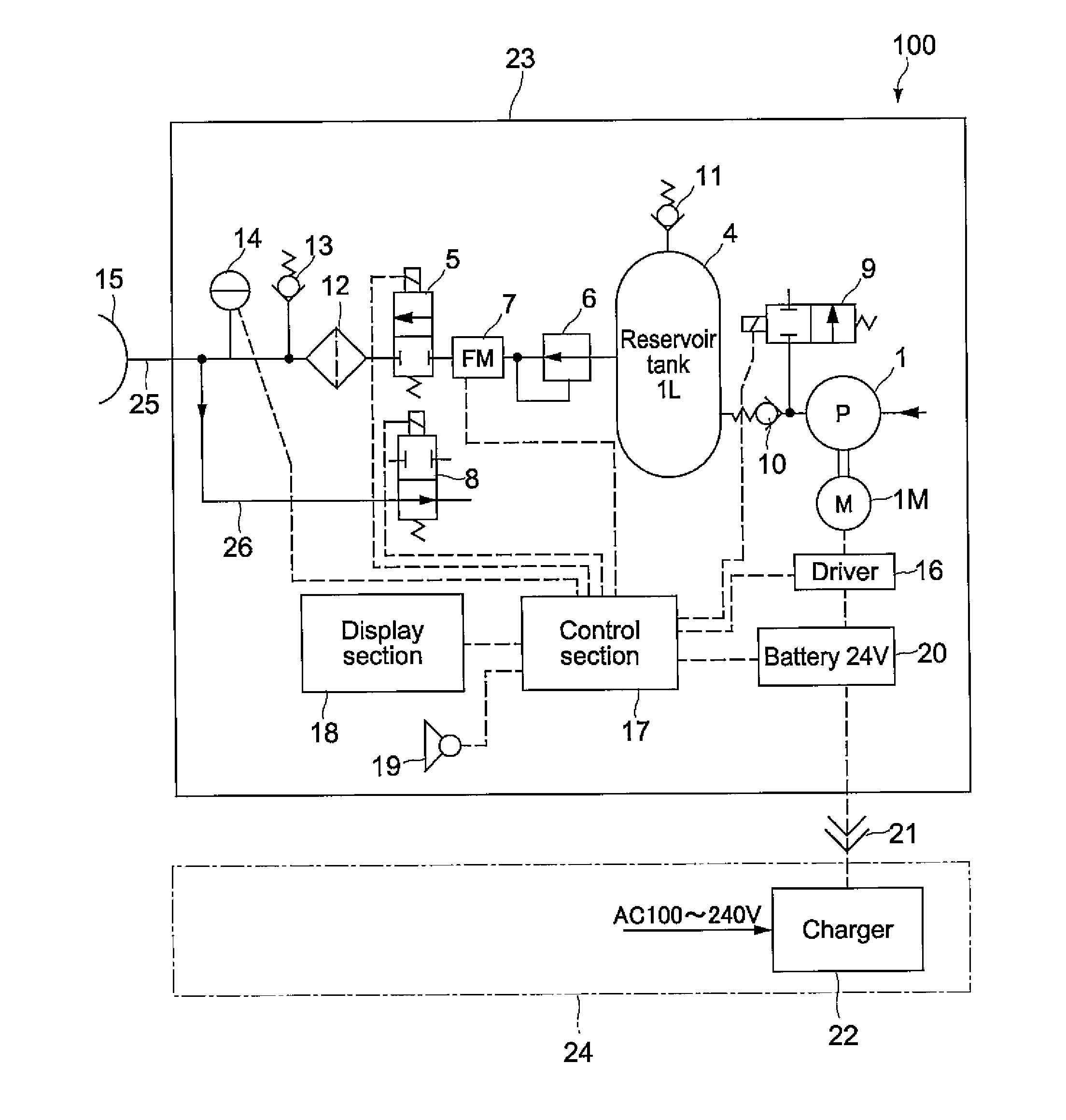
[0020]An artificial respirator according to an embodiment of the present invention includes a mask, a reservoir tank, a valve mechanism, a control section, and a pressurizing pump.

[0021]The mask is worn by the patient so as to cover the mouth and the nose, for example. The control section controls the valve mechanism to be driven, to thereby alternately switch between a first state for feeding inspiratory air stored in the reservoir tank to the patient and a second state for releasing expired air of the patient. The pressurizing pump has a discharge function for reversing a reduction of pressure within the reservoir tank, which is caused due to the inspiration, for an expiration period of time. Here, the expiration period of time (second period of time) is set to be equal to or longer than the inspiration period of time (first period of time), and hence the pressurizing pump having a small volume is allowed to supply needed inspiratory air into the reservoir tank. Thus, it is possib...


PUM


Abstract

To provide a compact and low-power-consumption artificial respirator and an operation method therefore including a controller which alternately switches between a first state for feeding inspiratory air stored in the reservoir tank to a patient and a second state for releasing expired air of the patient. A pressurizing pump has a discharge function for reversing a reduction of pressure within the reservoir tank, which is caused due to the inspiration, within an expiration period of time.

Description

TECHNICAL FIELD[0001]The present invention relates to an artificial respirator that supplies inspiratory air (inspiratory gas) when artificial respiration is performed on a user (patient) in a resuscitation procedure, and an operation method therefore.BACKGROUND ART[0002]In recent years, automatic external defibrillators (AED) have been permitted to be used by ordinary people other than the healthcare professionals such as doctors, emergency life saving technicians, nurses, and the like, and the AEDs have been widely provided at places where many people gather, such as airports, stations, and buildings, which contribute to increase the survival rate. In the resuscitation, cardiac arrest and respiration cease have to be handled. Although the AED is effective with respect to the cardiac arrest, for handling the respiration cease, artificial respiration (mouth to mouth, for example) is needed at the present time. Thus, if compact artificial respirators that are easy to be transported f...

Claims


Application Information

Patent Timeline
IPC IPC(8): A61M16/20A61M16/06
CPCA61M16/00A61M16/0057A61M16/06A61M2016/0021A61M2205/502A61M16/209A61M2205/8212A61M2205/8262A61M16/204A61M16/205A61M2205/58A61M16/0063A61M16/022
Inventor AIKAWA, JUNICHIWAKAMATSU, HIDETOSHIUTSUKI, TOMOHIKO
Owner ULVAC KIKO
Learn More