Ribbon microphone circuit

a microphone and ribbon technology, applied in the direction of deaf-aid sets, transducer details, electrical transducers, etc., can solve the problems of large output impedance, easy mixing of external noise, and increase of output impedance of ribbon microphone units

Inactive Publication Date: 2012-05-17
AUDIO-TECHNICA
View PDF0 Cites 4 Cited by
  • Summary
  • Abstract
  • Description
  • Claims
  • Application Information

AI Technical Summary

Benefits of technology

[0013]The present invention provides a ribbon microphone circuit that can output signals having a high level and a low impedance so that the circuit is barely affected by external noise.

Problems solved by technology

That is, the output level increases with an increase in the winding ratio N. The step-up transformer, however, causes an increase in output impedance of the ribbon microphone unit.
This may result in large output impedance that causes external noise to be easily mixed.
Such a large output impedance causes output signals to easily pick up noise during transmission through a cable, as generally known.

Method used


Image

  • Ribbon microphone circuit
  • Ribbon microphone circuit
  • Ribbon microphone circuit

Examples


Embodiment Construction

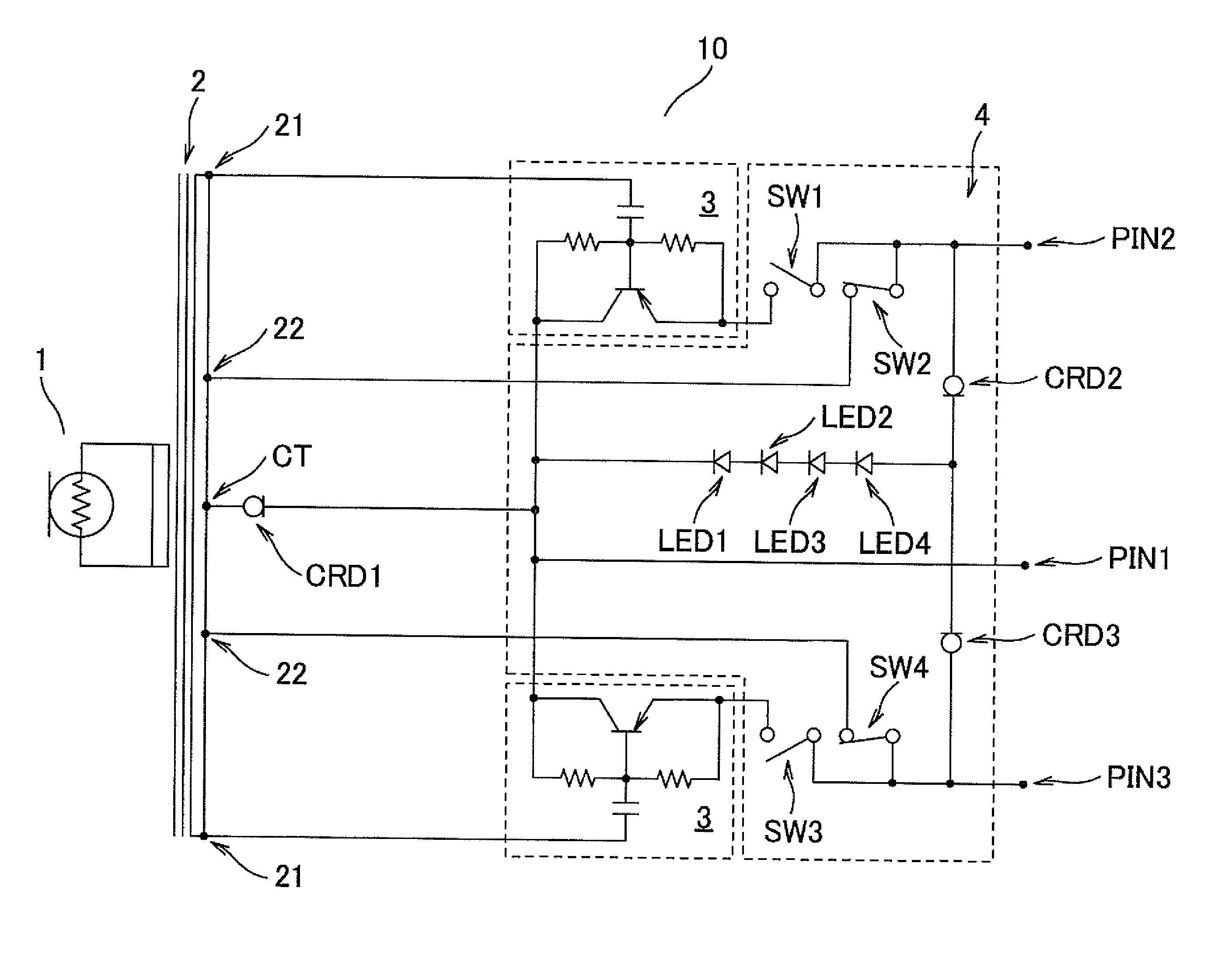
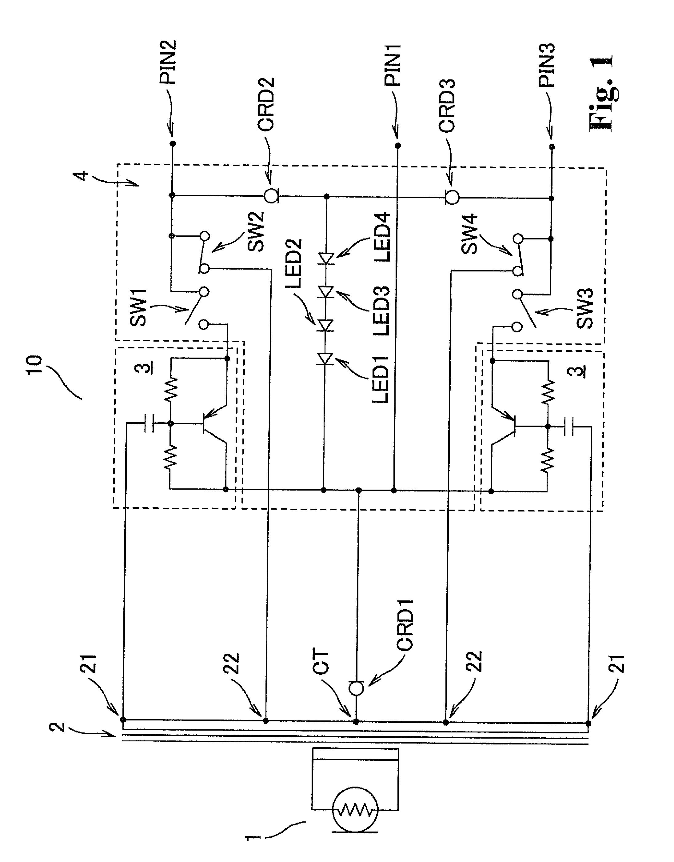
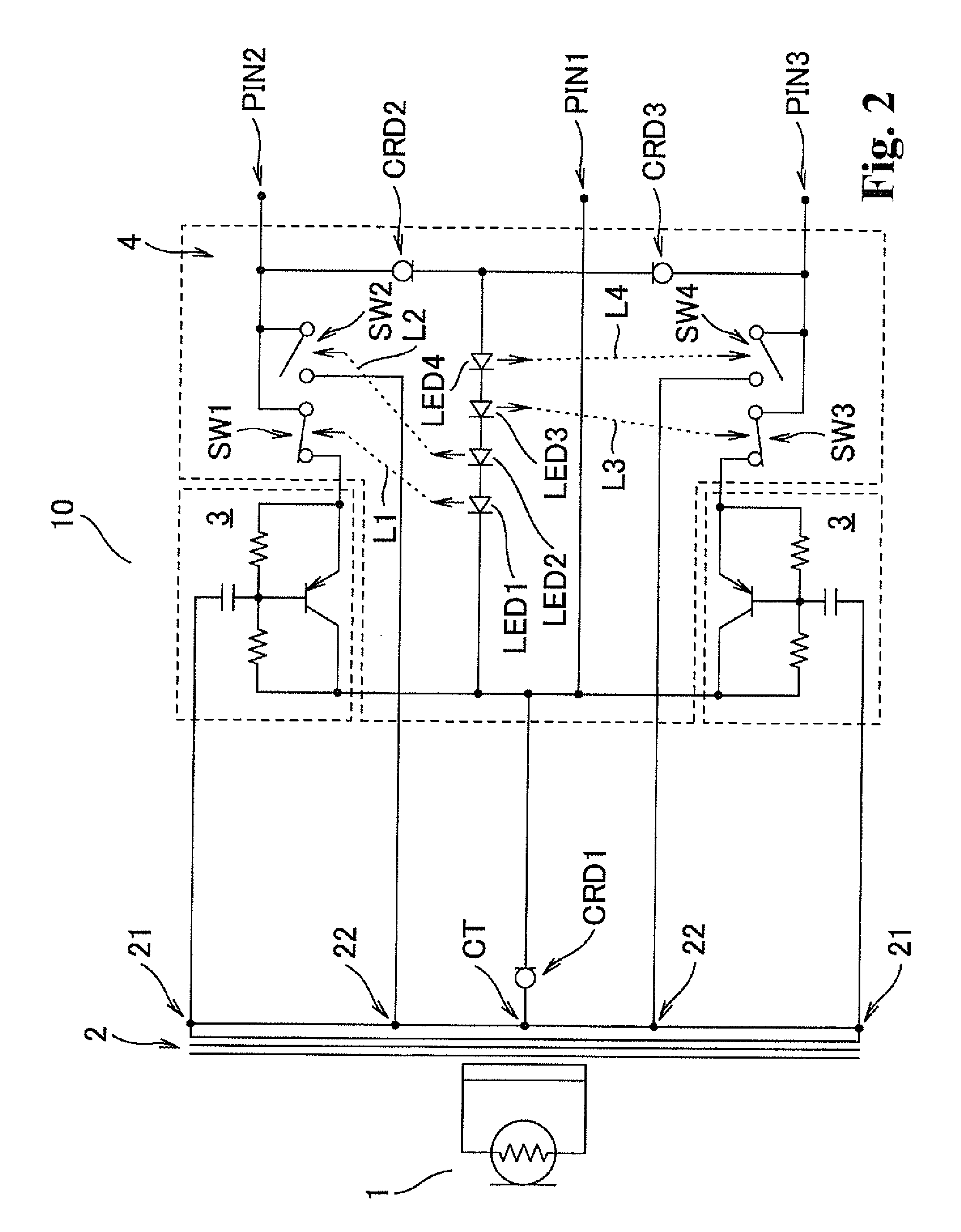
[0016]A ribbon microphone circuit according to an embodiment of the present invention is described below with reference to the attached drawings. FIG. 1 is a circuit diagram showing an exemplary ribbon microphone circuit according to the present invention. FIG. 1 shows a ribbon microphone circuit 10 including a ribbon microphone unit 1, a step-up transformer 2, buffer amplifier circuits 3, and a switch circuit 4.

[0017]The ribbon microphone unit 1 includes a ribbon diaphragm that is disposed in a parallel magnetic field and serves also as a conductor. The ribbon diaphragm vibrates in the magnetic field upon receiving sound waves and thus traverses a magnetic flux. An electric current flows through the diaphragm to generate electric signals having a frequency in proportion to the vibration frequency. The signal is output from output terminals provided at longitudinal ends of the ribbon diaphragm. The electric signals are produced through electroacoustic conversion in correspondence to...


PUM


Abstract

A ribbon microphone circuit includes a ribbon microphone unit; a step-up transformer; buffer amplifier circuits connected to a secondary winding of the step-up transformer; an external power supply circuit as a power source for driving the buffer amplifier circuits; and a switch circuit including photo-relays having lights that are turned on while the external power source is being supplied and having contacts operating depending on states of the respective lights, wherein signals output from the ribbon microphone unit are sent through the buffer amplifier circuits while the external power source is being supplied, and sent without passing through the buffer amplifier circuits while the external power source is being not supplied.

Description

BACKGROUND OF THE INVENTION[0001]1. Field of the Invention[0002]The present invention relates to a ribbon microphone circuit including an automatic switching system on the circuit configuration.[0003]2. Related Background Art[0004]A ribbon microphone, a type of dynamic microphone, can produce output without power sources. Since the output level from the ribbon microphone unit is low, a step-up transformer is typically connected to the output terminals of the unit. The ribbon microphone unit is connected to a primary winding of the transformer, and output terminals are provided across a secondary winding thereof. The ribbon microphone unit can output signals at a practical level.[0005]The step-up transformer boosts the output level of the ribbon microphone unit by N times, where N represents a winding ratio of the step-up transformer (1 / N=the number of primary winding / the number of secondary winding). That is, the output level increases with an increase in the winding ratio N. The st...

Claims


Application Information

Patent Timeline
Patent Type & Authority Applications(United States)
IPC IPC(8): H04R1/00
CPCH04R9/048H04R9/08
Inventor AKINO, HIROSHI
Owner AUDIO-TECHNICA
Why Eureka
Try Eureka