Gas generating system

a technology of gas generating system and gas generating system, which is applied in the directions of transportation and packaging, pedestrian/occupant safety arrangements, vehicular safety arrangements, etc., can solve the problems of cost and complexity of the system

Inactive Publication Date: 2012-05-24
JOYSON SAFETY SYST ACQUISITION LLC
View PDF18 Cites 29 Cited by
  • Summary
  • Abstract
  • Description
  • Claims
  • Application Information

AI Technical Summary

Problems solved by technology

An ongoing challenge in the design of vehicle occupant protection systems is to...

Method used


Image

  • Gas generating system
  • Gas generating system
  • Gas generating system

Examples


Embodiment Construction

[0012]In the descriptions set forth herein, like reference numerals refer to like elements of embodiments of the present invention.

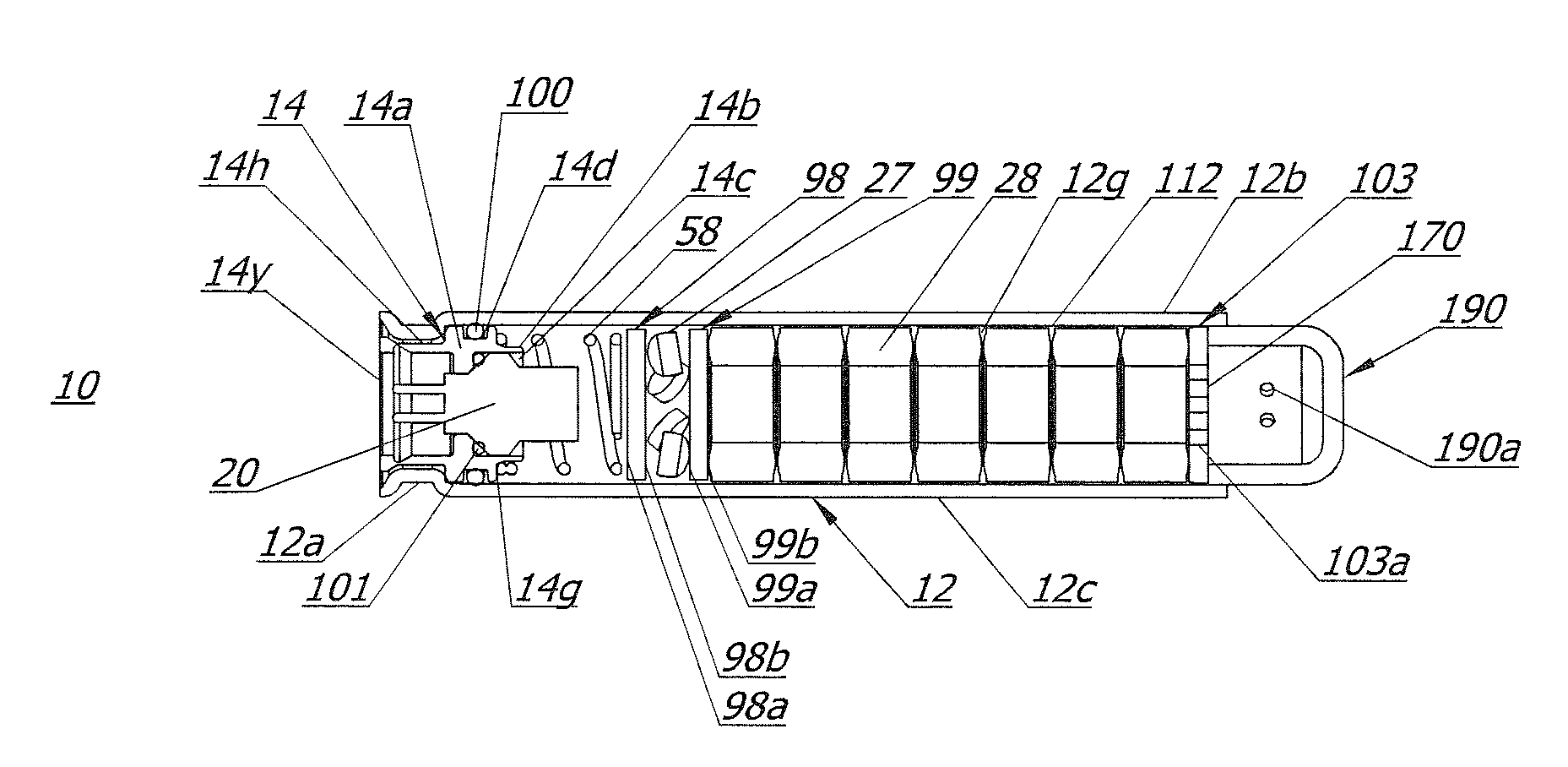
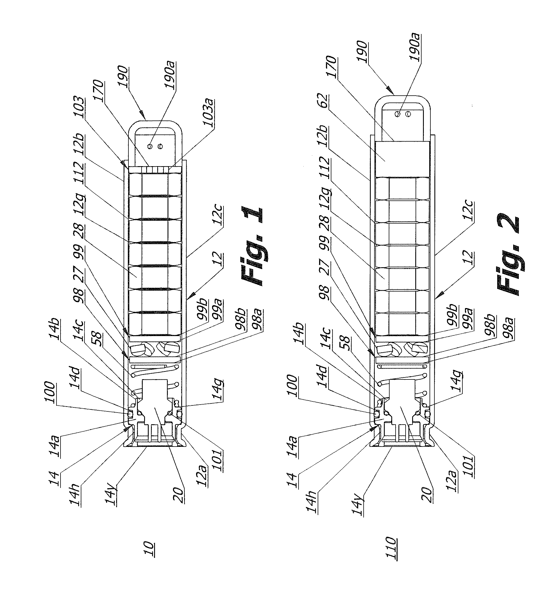
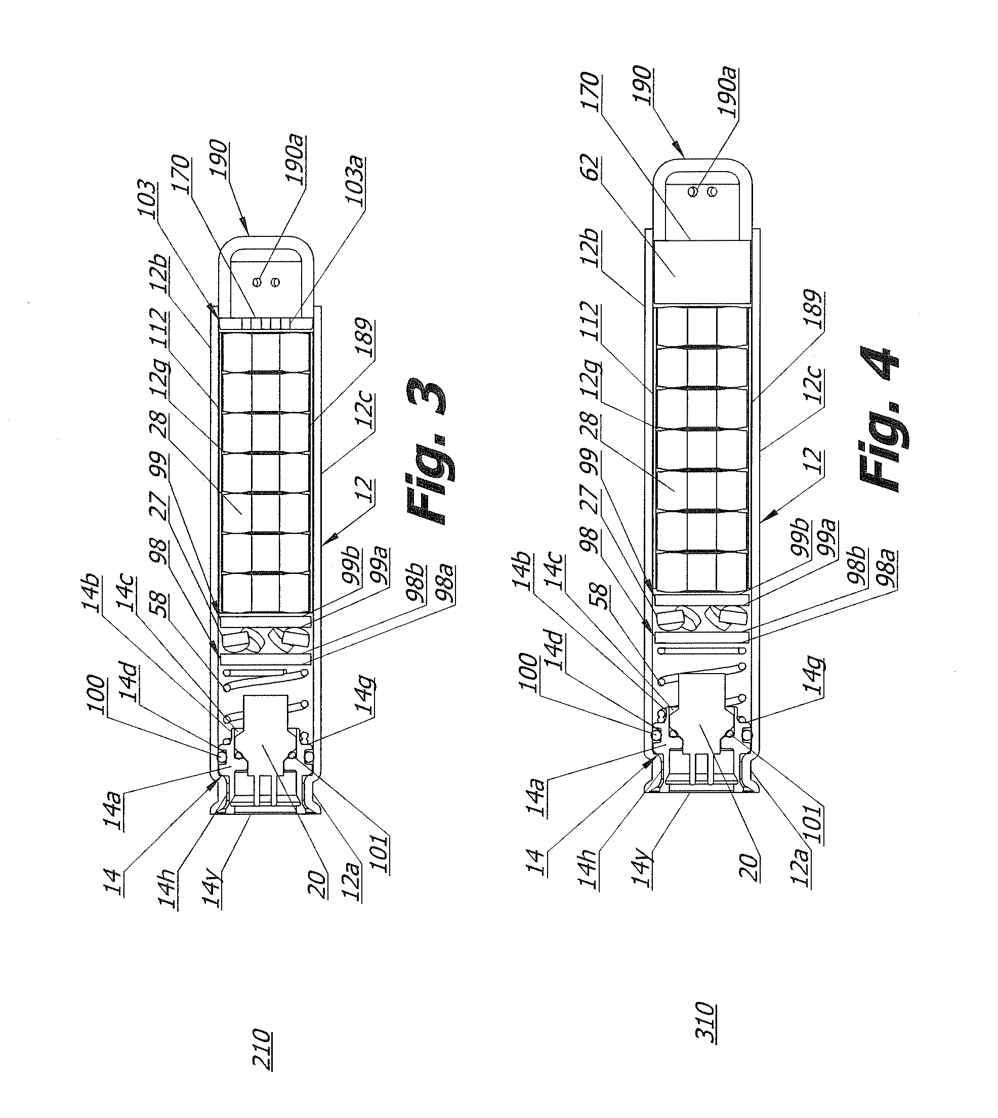
[0013]Referring to FIGS. 1-4, embodiments 10, 110, 210, 310 of a gas generating system include a substantially cylindrical housing 12 having a first end 12a, a second end 12b opposite the first end, and a wall 12c extending between the ends to define a housing interior cavity 112. A portion of cavity 112 defines a combustion chamber 12g for a combustible gas generant material 28 described in greater detail below. Housing 12 is made from a metal or metal alloy and may be a cast, stamped, deep-drawn, extruded, or otherwise metal-formed.

[0014]Housing first end 12a is configured for receiving a portion of a suitable initiator 20 (described below) therein, and is also configured to aid in retaining the initiator in place within the housing 12 once the initiator has been positioned. Housing end 12a may be structured so as to support and maintain initiator 20 i...


PUM


Abstract

A gas generating system includes a housing, a quantity of gas generant material positioned within the housing, and a quantity of booster material positioned in the housing spaced apart from the gas generant. A movable first screen is positioned in the housing such that the booster material is on a first side of the screen and the gas generant material is on a second side of the screen opposite the first side of the screen. The screen is structured to enable fluid communication between the first and second sides of the screen.

Description

CROSS REFERENCE TO RELATED APPLICATIONS[0001]This application claims the benefit of U.S. Provisional Application No. 61 / 417,138, filed on Nov. 24, 2010, the disclosure of which is incorporated by reference herein.BACKGROUND OF THE INVENTION[0002]The present invention relates to gas generating systems for generating pressurized gases used to inflate one or more inflatable devices.[0003]An ongoing challenge in the design of vehicle occupant protection systems is to reduce the cost and complexity of the system while meeting operational requirements. In protection systems utilizing gas generating systems or inflators to actuate inflatable elements of the protection system, it may be desirable for the gas generating system design to be flexible enough to enable the amount of gas generant and / or booster material incorporated to be varied according to the requirements of a particular application. It may also be desirable to enable incorporation of a means for shielding combustible material...

Claims


Application Information

Patent Timeline
IPC IPC(8): C06D5/00B60R21/26B01J7/00
CPCB60R21/2644B60R2021/26011B60R2021/2607B60R2021/2642C06C9/00B01J7/00B60R21/26B60R21/2646B60R21/264C06D5/00C06D5/06
Inventor MAYVILLE, BRIAN A.TAUCHEN, DALE E.VANHOOSER, JOSHUA D.
Owner JOYSON SAFETY SYST ACQUISITION LLC
Why Eureka
Try Eureka