Method and Apparatus for Forming and Mounting a Photovoltaic Array
a photovoltaic array and photovoltaic technology, applied in the direction of heat collector mounting/support, lighting and heating apparatus, rod connection, etc., can solve the problems of other limitations of the related art, and achieve the effect of rapid twist-lock engagement and improved structural load distribution
- Summary
- Abstract
- Description
- Claims
- Application Information
AI Technical Summary
Benefits of technology
Problems solved by technology
Method used
Image
Examples
first embodiment
[0089]The first embodiment of the present invention provides numerous advantages over prior art systems. Inventive features of the present apparatus include, but are not limited to the following:
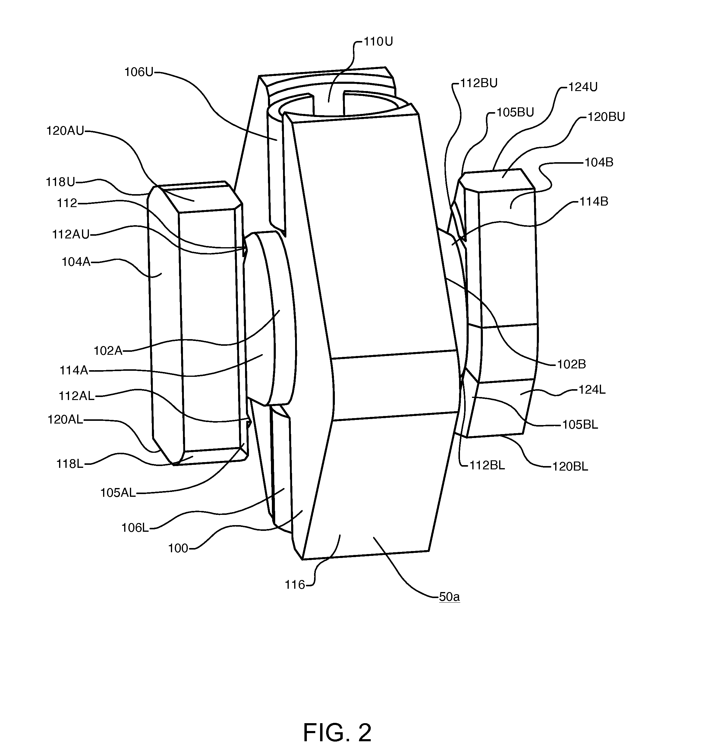
[0090]Parallel coupling action—parallel coupling is attachable to substantially the whole length of all four sides of a PV module and securely locks the outside surfaces of parallel frame members together in a side to side arrangement, thereby increasing the structural performance of the PV array.
[0091]Three mode design—Parallel coupling is shiftable with a wrench into three modes of operation: positioning mode, sliding mode, and locked mode. A positive stop is provided when locked mode is reached.
[0092]Locking portion—Parallel coupling provides two specially shaped locking portions which are insertable into slots on the outside surfaces of adjacent frame members. Locking portions enable discrete positions of device and provide a positive stop for locked position.
[0093]Dual bearing action—Pa...
second embodiment
[0118]FIG. 31 is the same as FIG. 11 except that PV array 10 utilizes the framing and coupling system of the second embodiment. Brackets 132 are shown in the same locations except now they are connected to frames 212A, 212B, 212C, 212D via couplings 50j, thereby reducing total part count and installation time required for PV array 10. Series-parallel couplings 50b bridge the corner points where the four corners of PV modules 211A, 211B, 211C, 211D meet. For example, a coupling 50b is shown bridging a corner point 295 where four PV modules 211A, 211B, 211C, 211D meet. Parallel coupling portions 50bb interlock modules 211A, 211B and 211C, 211D while series coupling portion 162 interlocks modules 211B, 211D and 211A, 211C. Please note that a second series coupling portion between 211A, 211C is possible but not required since parallel coupling portions 50bb lock frame 212A to frame 212B and frame 212C to frame 212D along with series coupling portion 162.
[0119]Thus, the two axis parallel...
third embodiment
[0129]FIGS. 32-34 depict a third embodiment of the present invention. This embodiment is similar to the first embodiment described above except that the orientation of the coupling action of coupling 50a has been altered and a retaining element has been added. Instead of bearing against vertically oriented opposing surfaces on frame 12, a parallel coupling 50c is provided to bear against horizontally oriented opposing surfaces on frame 12.
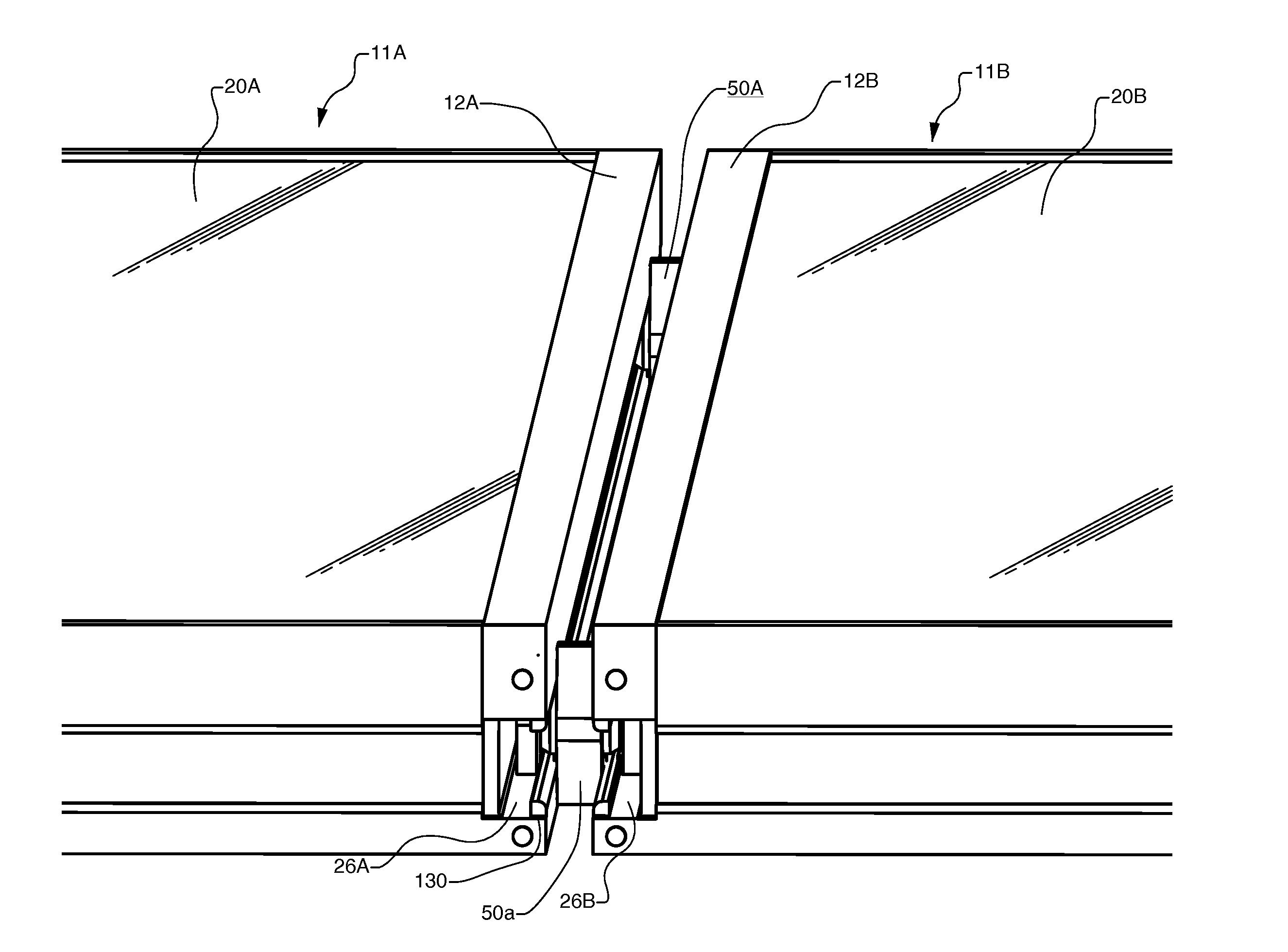
[0130]FIG. 32 shows a perspective view of parallel coupling 50c which has been installed into slots 26A, 26B of two adjacent PV modules 11A, 11B but not fully tightened down. Frames 12A, 12B have been cut away so that coupling 50c shows in this view. FIG. 33 provides an exploded view of the two sides of a retainer portion 354L, 354R. FIG. 34 provides a cross-section view cut through two adjacent PV modules 11A, 11B which are coupled together with parallel coupling 50c. The cross section is cut partially through coupling 50c as indicated.
[0131]Refer...
PUM
 Abstract
Description
Claims
Application Information
 - R&D
- Intellectual Property
- Life Sciences
- Materials
- Tech Scout
- Unparalleled Data Quality
- Higher Quality Content
- 60% Fewer Hallucinations
Browse by: Latest US Patents, China's latest patents, Technical Efficacy Thesaurus, Application Domain, Technology Topic, Popular Technical Reports.
© 2025 PatSnap. All rights reserved.Legal|Privacy policy|Modern Slavery Act Transparency Statement|Sitemap|About US| Contact US: help@patsnap.com


