
Button mechanism and electronic device therewith

Active Publication Date: 2012-06-07
WISTRON CORP
View PDF3 Cites 0 Cited by
  • Summary
  • Abstract
  • Description
  • Claims
  • Application Information

AI Technical Summary

Benefits of technology

[0006]An objective of the present invention is to provide a button mechanism utilizing an actuating structure to trigger a plurality of electrode layers, and the button mechanism has small dimension and preferable reliability.
[0007]Another objective of the present invention is to provide an electronic device. The electronic device has the button mechanism utilizing an actuating structure to trigger a plurality of electrode layers, and the button mechanism has small dimension and preferable reliability.
[0017]The button mechanism and the electronic device of the present invention not only economizes disposal space of the substrate, but also conforms to design specification of the button mechanism, so that the actuating structure and the two electrode layers of the button mechanism can have effective contacting areas for decreasing contact impedance and for preferable conductive reliability. In addition, no matter where the actuating structure is pressed, the conducting portion can be electrically connected to the first electrode layer and the second electrode layer. Thus, the button mechanism of the present invention can be applied to the electronic product with a small size for preferable durability.

Problems solved by technology

For conforming to design specification and reliability test of the button structure 10, the conventional button structure 10 has large volume, so that it is difficult to arrange position and number of the button structure in limited mechanical space of the electronic device.
Thus, design of the button structure having small dimension and preferable reliability is an important issue of the button mechanism.

Method used


Image

  • Button mechanism and electronic device therewith
  • Button mechanism and electronic device therewith
  • Button mechanism and electronic device therewith

Examples


first embodiment

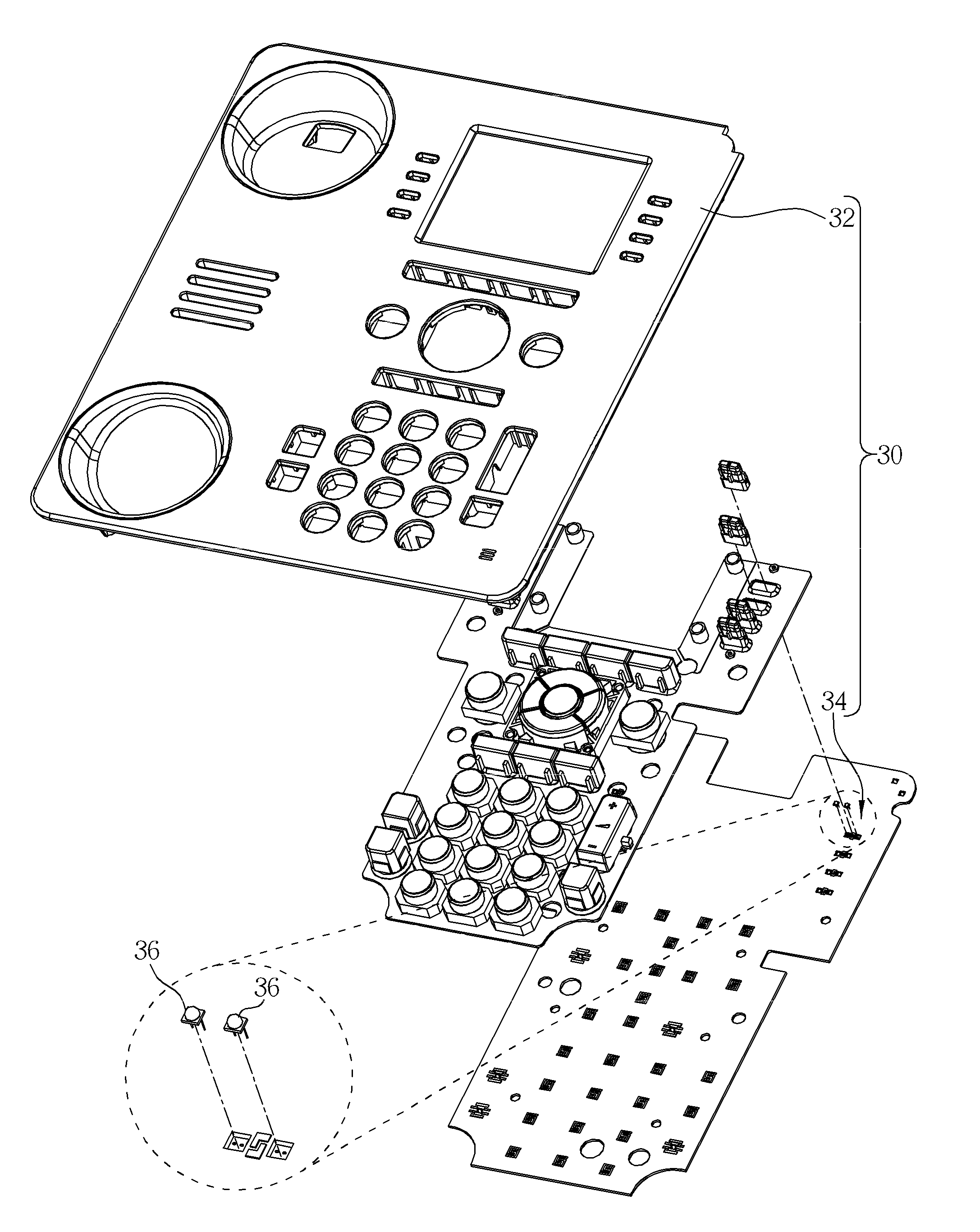
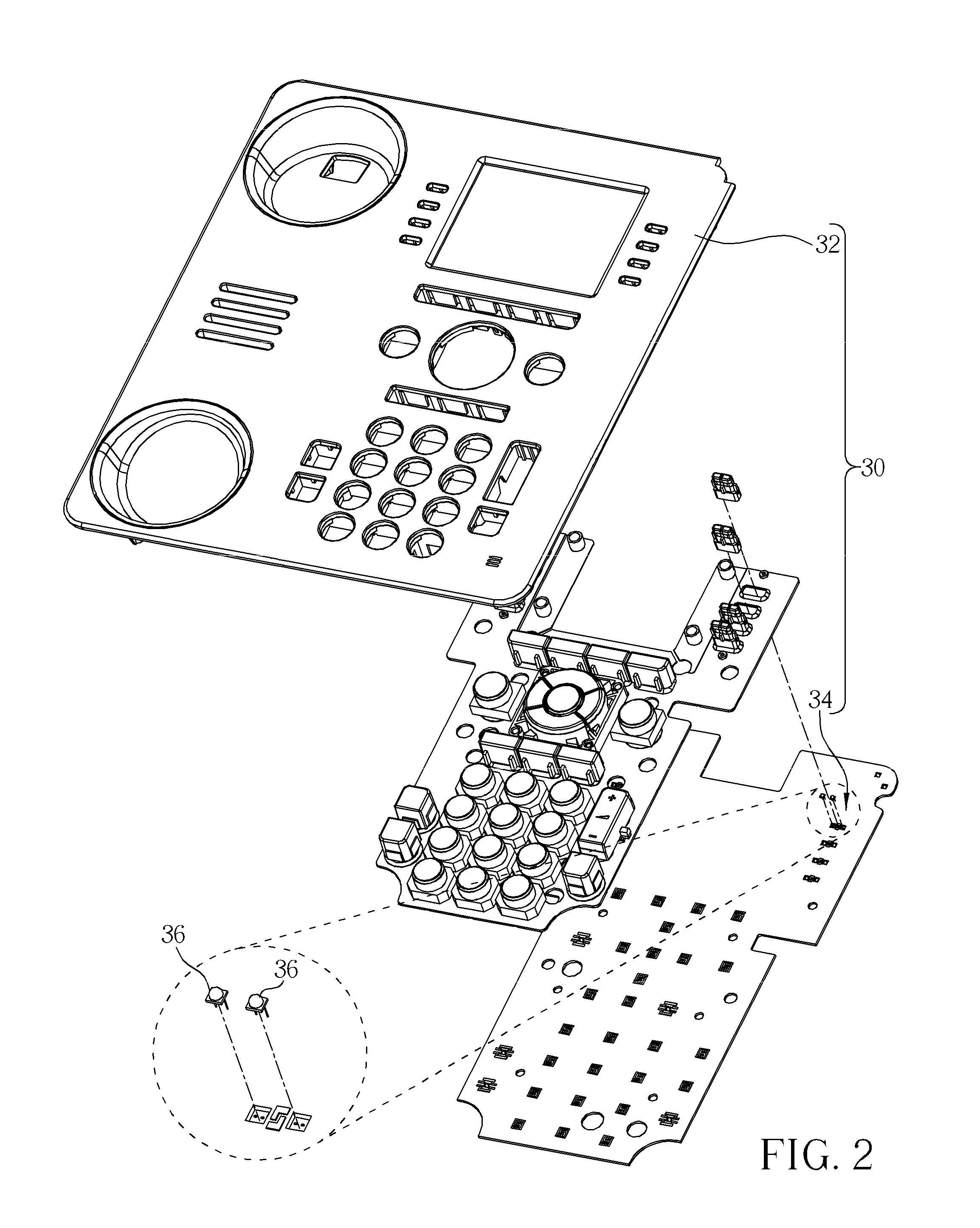
[0025]Please refer to FIG. 2. FIG. 2 is an exploded diagram of the electronic device according to the present invention. For example, the electronic device 30 can be a VOIP telephone, a mobile phone, a personal digital assistant (PDA), a notebook computer, and so on. The electronic device 30 includes a casing 32, a button mechanism 34, and at least one lighting unit 36. The button mechanism 34 is disposed inside the casing 32, and the lighting unit 36 is disposed adjacent to the button mechanism 34. The lighting unit 36 emits light corresponding to operation modes of the button mechanism 34. For example, the lighting unit 36 emits green light when the telephone is available, and the lighting unit 36 emits red light when the telephone is busy. In the embodiment, the lighting unit 36 can be a light emitting diode (LED), and there are two lighting units 36.

[0026]Please refer to FIG. 3. FIG. 3 is a diagram of the button mechanism 34 according to the first embodiment of the present inven...

third embodiment

[0044]In the third embodiment, the first electrode layer 46b and the second electrode layer 50b of the circuit structure are respectively U-typed electrode layers. The predetermined interval between the first electrode layer 46b and the second electrode layer 50b includes four turning portions 521b.

[0045]It should be mentioned that shapes of the first electrode layer and the second electrode layer of the button mechanism of the present invention are not limited to the above-mentioned embodiment. For example, the shapes of the first electrode layer and the second electrode layer can be trapezoids, hooks and so on.

[0046]In conclusion, the button mechanism and the electronic device of the present invention can guide the light emitted from the at least one lighting unit to the casing. The circuit structure of the button mechanism has small size that not only economizes disposal space of the substrate, but also conforms to design specification of the substrate, the electrode layers and ...


PUM


Abstract

A button mechanism includes a circuit structure and an actuating structure. The circuit structure includes a substrate, a first electrode layer, and a second electrode layer. The first electrode layer and the second electrode layer are disposed on the substrate, and the second electrode layer is separated from the first electrode layer. The first electrode layer includes a first section and a second section. The second electrode layer includes a third section and a fourth section. The second section stretches to the third section, and the fourth section stretches to the first section. A predetermined gap is formed between the first electrode layer and the second electrode layer, and the predetermined gap includes a plurality of curved portions. The actuating structure includes a conductive portion for conducting the first electrode layer and the second electrode layer.

Description

BACKGROUND OF THE INVENTION[0001]1. Field of the Invention[0002]The present invention relates to a button structure, and more particularly, to a button structure having small volume and utilizing an actuating structure to trigger a plurality of electrode layers and an electronic device therewith.[0003]2. Description of the Prior Art[0004]Please refer to FIG. 1. FIG. 1 is a diagram of a button mechanism in the prior art. A button mechanism 10 includes a circuit structure 12 and an actuating structure 14. The circuit structure 12 includes a substrate 16 and two U-typed electrode layers 18. The U-typed electrode layers 18 are alternately disposed on the substrate 16. A predetermined interval is formed between the two U-typed electrode layers 18 for preventing signal interference due to close distance of the two U-typed electrode layers 18. The actuating structure 14 is for contacting with the U-typed electrode layers 18 simultaneously, so as to electrically connect the two electrode la...

Claims


Application Information

Patent Timeline
IPC IPC(8): H01H13/02
CPCH01H13/023H01H13/79H01H2203/02H04M1/23H01H2205/016H01H2219/062H04M1/22H01H2203/036
Inventor LEE, HSIN-CHUNHUANG, CHIN-LILAI, NIEN-ANKUO, YU-LING
Owner WISTRON CORP
Features
  • Generate Ideas
  • Intellectual Property
  • Life Sciences
  • Materials
  • Tech Scout
  • Unparalleled Data Quality
  • Higher Quality Content
  • 60% Fewer Hallucinations
Learn More