
LED Light Brick Attachment Device

a technology of led light bricks and attachment devices, which is applied in the direction of lighting and heating apparatus, light support devices, point-like light sources, etc., can solve the problems of power disruption to the remaining light bricks, difficulty in securing the light bricks in this position, and appearance of holes or breaks in the lighting chain, so as to prevent undesired slippage

Inactive Publication Date: 2012-06-21
QUALITY NEON SIGN
View PDF3 Cites 0 Cited by
  • Summary
  • Abstract
  • Description
  • Claims
  • Application Information

AI Technical Summary

Benefits of technology

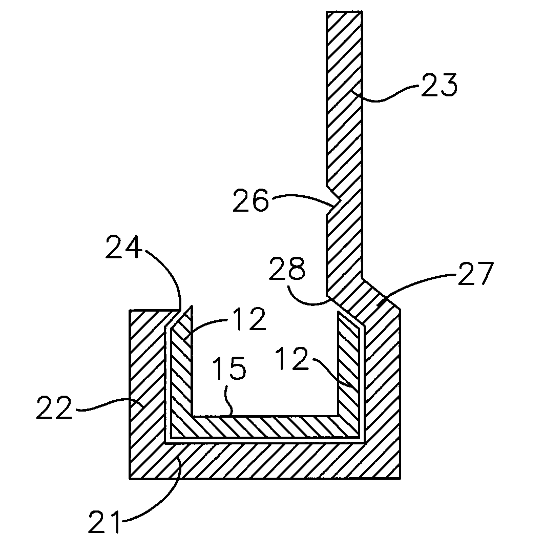
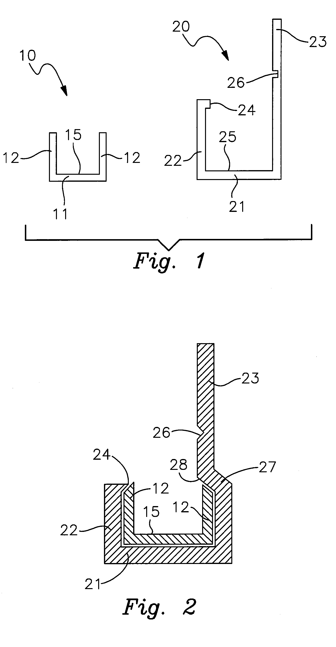
[0006]In one embodiment, the second vertical stem further comprises an offset that shifts an upper portion of the second stem toward the trough of the clip. The offset forms an indented surface, or shoulder, capable of retaining one of the vertical sides of the channel, which further prevents the channel from being inadvertently dislodged from the J-shaped clip. In another embodiment, the attachment device additionally comprises a retaining clip capable of fitting over the first stem and vertical side of the channel, which prevents undesired slippage between the light brick and the channel. The channel can further comprise a means for anchoring the channel to a structural support, where such anchoring means could be threaded fasteners, brackets, glue, epoxy, clips, hangars, or the like.

Problems solved by technology

However, securing the light bricks in this position may be difficult, particularly where the light bricks are used to illuminate an existing structure, such as a building, sign, monument, walkway, or other such structure.
Unreliable attachment devices can cause the light bricks to become dislodged from their desired position, thus creating the appearance of holes or breaks in the lighting chain.
When the light bricks are dislodged, the wires connecting the light bricks are sometimes damaged, causing a power disruption to the remaining light bricks.
Previous attachment systems for light bricks are cumbersome to use, install, and adjust.

Method used


Image

  • LED Light Brick Attachment Device
  • LED Light Brick Attachment Device
  • LED Light Brick Attachment Device

Examples


Embodiment Construction

[0011]With reference to the drawings, the invention will now be described with regard for the best mode and the preferred embodiment. In general, the invention comprises an attachment device for retaining or mounting standard LED light bricks to signs, walls, or other support structures. The embodiments disclosed herein are meant for illustration and not limitation of the device. An ordinary practitioner will understand that it is possible to create other variations of the following embodiments without undue experimentation.

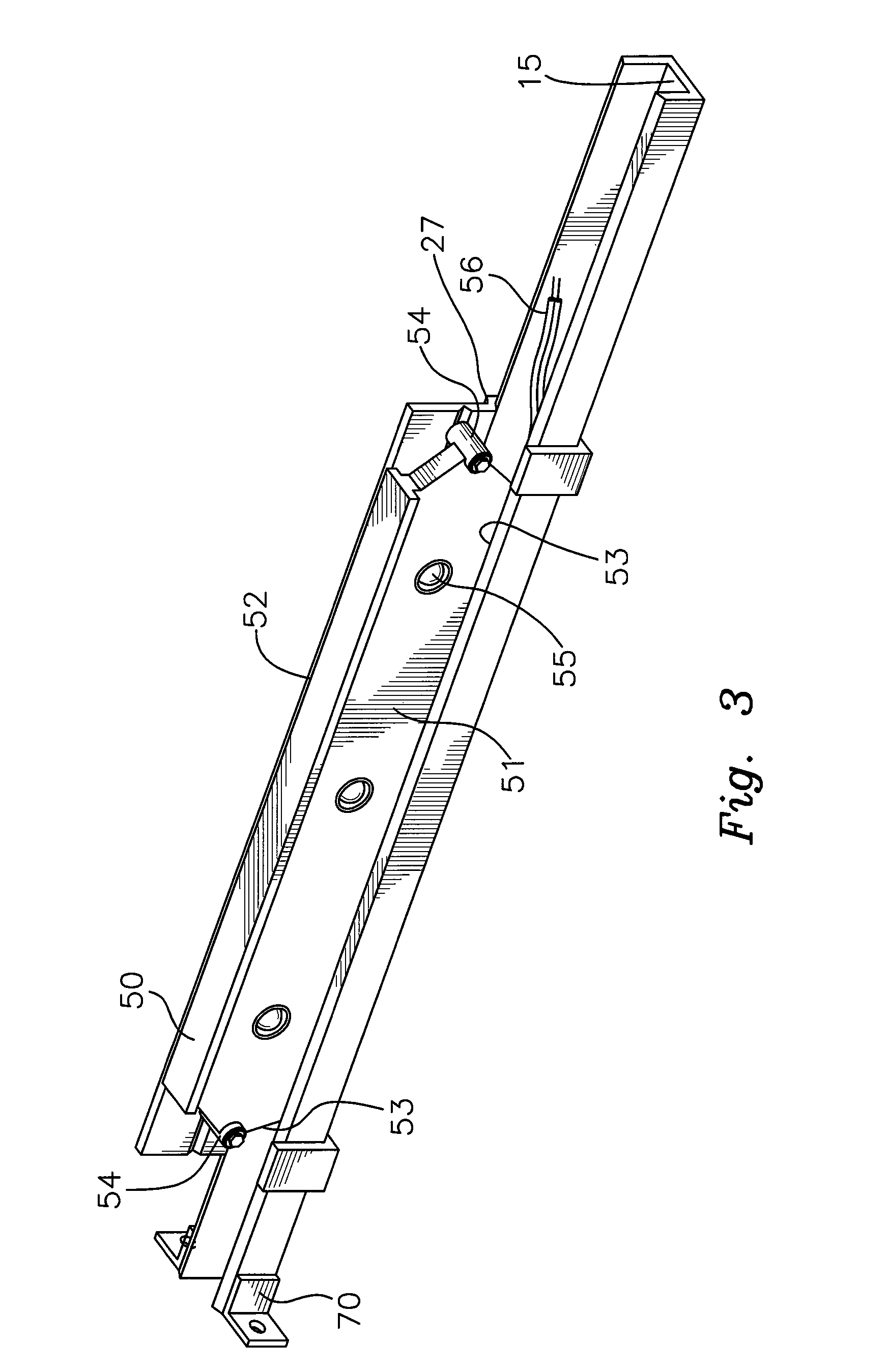
[0012]Referring to FIGS. 1 and 2, the attachment device generally comprises a U-shaped channel 10 and one or more generally J-shaped clips 20, the combination of which is capable of attaching a standard LED light brick 50 (shown in FIGS. 3 and 4) to a wall, sign, or other support structure. The channel 10 and clip 20 can be made of a variety of plastics, metals, alloys, or like material. These components can be made by extrusion or cold forming as appropriate. Th...


PUM


Abstract

A LED light brick attachment device comprising a U-shaped channel and one or more generally J-shaped clips, the combination of which is capable of attaching a standard LED light brick to a support structure. The channel is defined by a base and two vertical sides, forming a trough capable of slideably seating a flange of a standard LED light brick. The clip is defined by a base, a first stem, and an elongated second stem, the base, first stem, and an elongated second stem forming a J-shaped cross-section having a trough. The top of the first stem has an inwardly protruding retaining lip. The second stem has an engagement means capable of engaging a fastener on the light brick. The trough of the clip is capable of being snugly disposed about the channel such that the retaining lip of the first vertical stem is snugly disposed above to the top of one of the vertical sides of the channel, which prevents the channel from being dislodged from the clip.

Description

BACKGROUND OF THE INVENTION[0001]The present invention relates generally to elongate lighting devices, and more specifically to attachment devices for extended lengths of light emitting diodes (“LED”). LED lighting is commercially available in prefabricated, rigid units or clusters, often called “LED light bricks.” Each brick, which is typically made of plastic, can comprise multiple LED lights. The light bricks can be arranged as desired to solve a wide variety of lighting problems. For example, it is known to use LED light bricks in landscape or accent lighting, security lighting, storefront signage, and emergency exit illumination, to name a few typical applications.[0002]In many applications, it is desirable to arrange multiple LED light bricks in series so that the light bricks form a chain, row, or line of LED lights. However, securing the light bricks in this position may be difficult, particularly where the light bricks are used to illuminate an existing structure, such as a...

Claims


Application Information

Patent Timeline
Patent Type & Authority Applications(United States)
IPC IPC(8): F21V21/088
CPCF21V21/088F21Y2103/003F21Y2101/02F21S4/003F21S4/20F21Y2103/10F21Y2115/10
Inventor WILLIAMS, ROGER S.BELL, DANIEL
Owner QUALITY NEON SIGN
Learn More