Assembly of a Multipole Switchgear Device With Double Enclosure and Circuit Breaker Comprising the Same

a multi-pole switchgear and circuit breaker technology, applied in the field of modular low-voltage multi-pole circuit breaker, can solve the problems of single breaking exceeding the limits of certain electric performances, complex assembly, and difficulty in connection

Active Publication Date: 2012-06-28
SCHNEIDER ELECTRIC IND SAS
View PDF6 Cites 0 Cited by
  • Summary
  • Abstract
  • Description
  • Claims
  • Application Information

AI Technical Summary

Benefits of technology

[0004]Among other advantages, the object of the invention is to palliate the shortcomings of existing multipole switchgear apparatuses with double enclosure. In particular, the object of the invention is to take maximum advantage of the modularity provided by the use of single-pole breaking cartridges and standardization of the trip devices.
[0006]Another object of the invention is the ruggedness of the switchgear device over a low-voltage range up to 630 A, or even 800 A, while at the same time keeping the height dimension of the device within the available values to avoid problems of fitting in panels. For example, for a 160 A circuit breaker, the “overall” height of the switchgear device, i.e. without accessories, is about 130 mm.
[0016]The spacers and single-pole units, one of which is coupled with an actuating mechanism, are secured to one another. Advantageously, the breaking units are guided in sliding on the spacers so as to facilitate fitting and to take the stresses up directly. The unit formed by the single-pole units and spacers is associated with simultaneous drive means, in particular a pass-through rod, and suitable connection terminals may be associated with the line-side connection terminal strips. The whole assembly is closed by side walls at each end, each wall preferably comprising two similar edges to those of the spacers and the corresponding arrangements on one of its faces, so as to form a multipole switchgear device which can be associated with a trip device and / or a closing cover to form a switchgear apparatus of circuit breaker type with double enclosure. Advantageously, the trip device is guided in sliding on the cartridges or on the spacers of the switchgear device so as to facilitate fitting and securing. The securing means of the trip device on the multipole switchgear device are preferably guided in suitable means, of guide hole type, of the spacers to increase the mechanical strength.

Problems solved by technology

However, single breaking reaches its limits for certain electric performances.
Furthermore, existing rotary double breaking devices are based on insertion via the front of the trip device 7, i.e. via the face comprising the nose 9 and the handle of the circuit breaker 1, which gives rise to difficulties of connection and complex assembly.

Method used


Image

  • Assembly of a Multipole Switchgear Device With Double Enclosure and Circuit Breaker Comprising the Same
  • Assembly of a Multipole Switchgear Device With Double Enclosure and Circuit Breaker Comprising the Same
  • Assembly of a Multipole Switchgear Device With Double Enclosure and Circuit Breaker Comprising the Same

Examples


Embodiment Construction

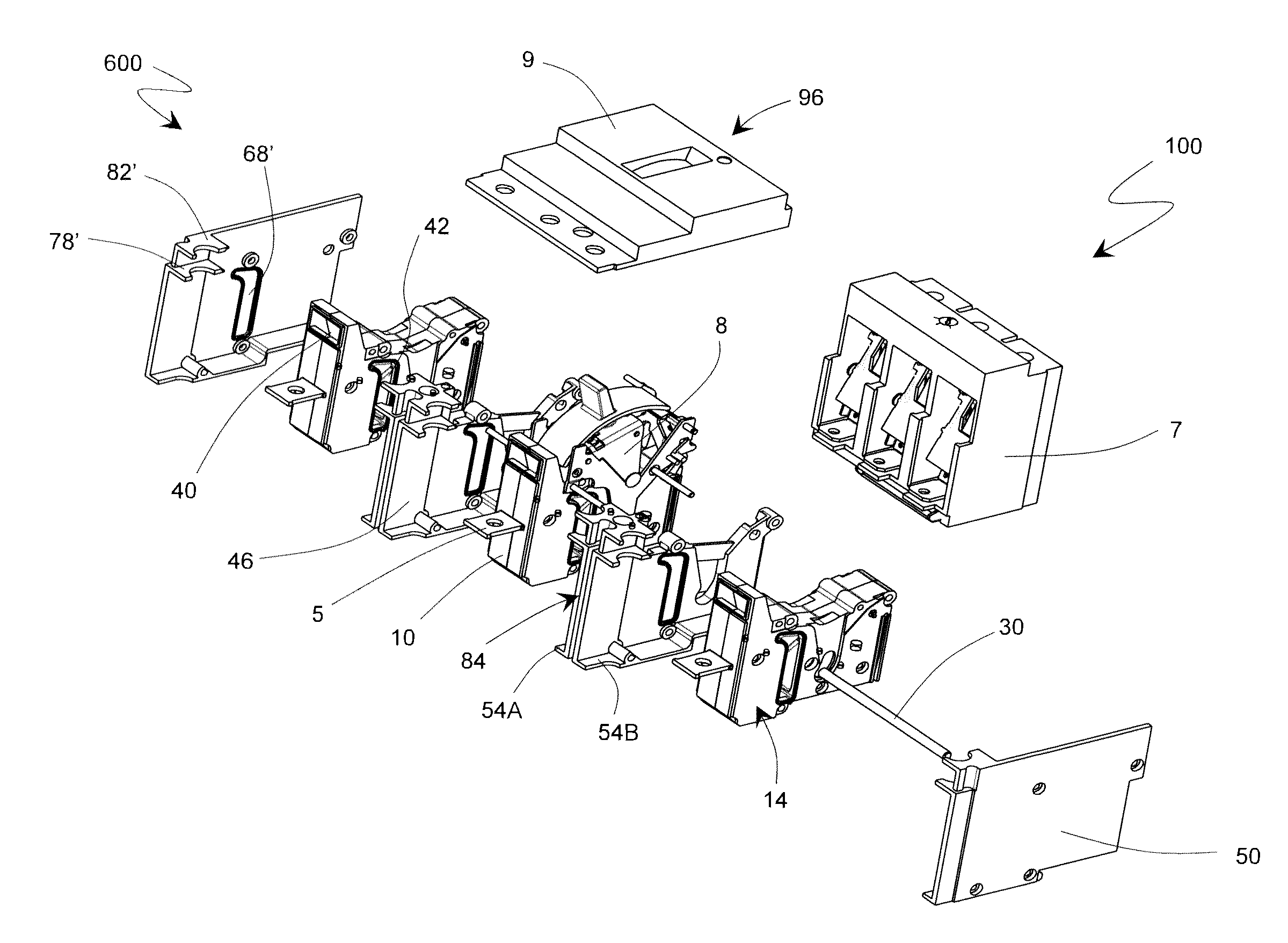
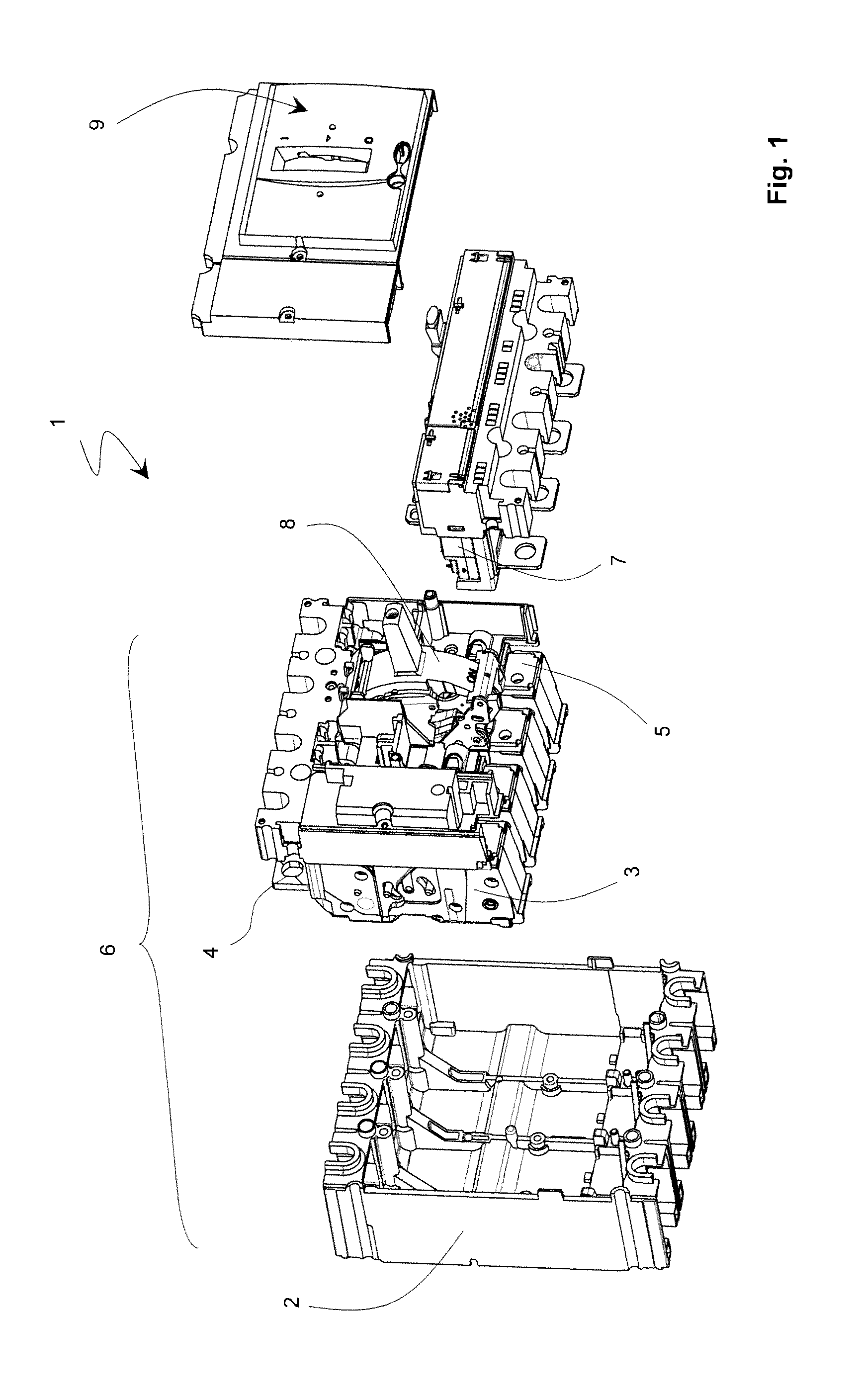
[0024]With a concern for simplification of presentation of a preferred embodiment of the invention, the elements composing the switchgear apparatus 1, and in particular the single-pole cartridges 3 forming the breaking device 6, will be described in relation with the position of use in which the circuit breaker 1 is fitted in place in a panel, the opposite to FIG. 1, with the nose 9 comprising the vertical handle parallel to the wall or mounting plate, the line-side connection terminal strips 4 on the electric line located at the top and the trip device 7 at the bottom. The use of the relative position terms such as “lateral”, “top”, “bottom”, etc. should not be interpreted as a limiting factor.

[0025]A multipole switchgear apparatus according to the invention 100, generally a circuit breaker, comprises a trip device 7 associated with a breaking device 600 comprising a plurality of cartridges 10, or single-pole breaking units, each unit 10 performing breaking of a single pole and bei...


PUM


Abstract

In order to take maximum advantage of the modularity provided by a multipole circuit breaker with double enclosure (100), a new architecture is proposed. The outer case (48) of the switchgear apparatus (100) is formed directly when assembly of the breaking device (600) is performed by juxtaposition and securing between single-pole breaking units (10), spacers (46) and side walls (50), trip device (7) and cover (64). The spacers (46) can thus be used for various functionalities, and in particular to modify the external aspect of the switchgear apparatus (100) or the nature of the trip device (7) in delayed manner.

Description

TECHNICAL FIELD[0001]The invention relates to a modular low-voltage multipole circuit breaker wherein a trip device is common to all the poles which each comprise an independent breaking cartridge. The invention relates to a new architecture for this type of circuit breakers in which the conventional double enclosure is modified to optimize the modularity for different functions and / or sizes to be parameterized in the circuit breaker.STATE OF THE ART[0002]A conventional low-voltage multipole switchgear apparatus 1, generally a circuit breaker, as described in EP 0 542 636 and illustrated in FIG. 1, comprises a double enclosure: an outer case 2 of the circuit breaker 1 houses a plurality of single-pole current breaking units 3 between a line-side terminal strip 4 connected to the line to be protected and a load-side terminal strip 5. The set of units 3 in the case 2 forms the breaking device 6 which is connected to a single trip device 7 at the level of the load-side terminal strips ...

Claims


Application Information

Patent Timeline
Patent Type & Authority Applications(United States)
IPC IPC(8): H01H9/02
CPCH01H1/2058H01H2071/0285H01H71/0235H01H13/70
Inventor NEREAU, JEAN-PIERREGRUMEL, CHRISTOPHERIVAL, MARCANGLADE, HERVÉ
Owner SCHNEIDER ELECTRIC IND SAS
Why Eureka
Try Eureka