Electronic trip device case for a circuit breaker, electronic trip device and assembly method thereof

a circuit breaker and electronic technology, applied in the direction of substations, non-enclosed substations, magnetic bodies, etc., can solve the problems of cumbersome circuit breaker assembly procedures and inability to minimize space requirements inherent in these functionalities, and achieve the effect of facilitating assembly

Active Publication Date: 2013-01-22
SCHNEIDER ELECTRIC IND SAS
View PDF28 Cites 14 Cited by
  • Summary
  • Abstract
  • Description
  • Claims
  • Application Information

AI Technical Summary

Benefits of technology

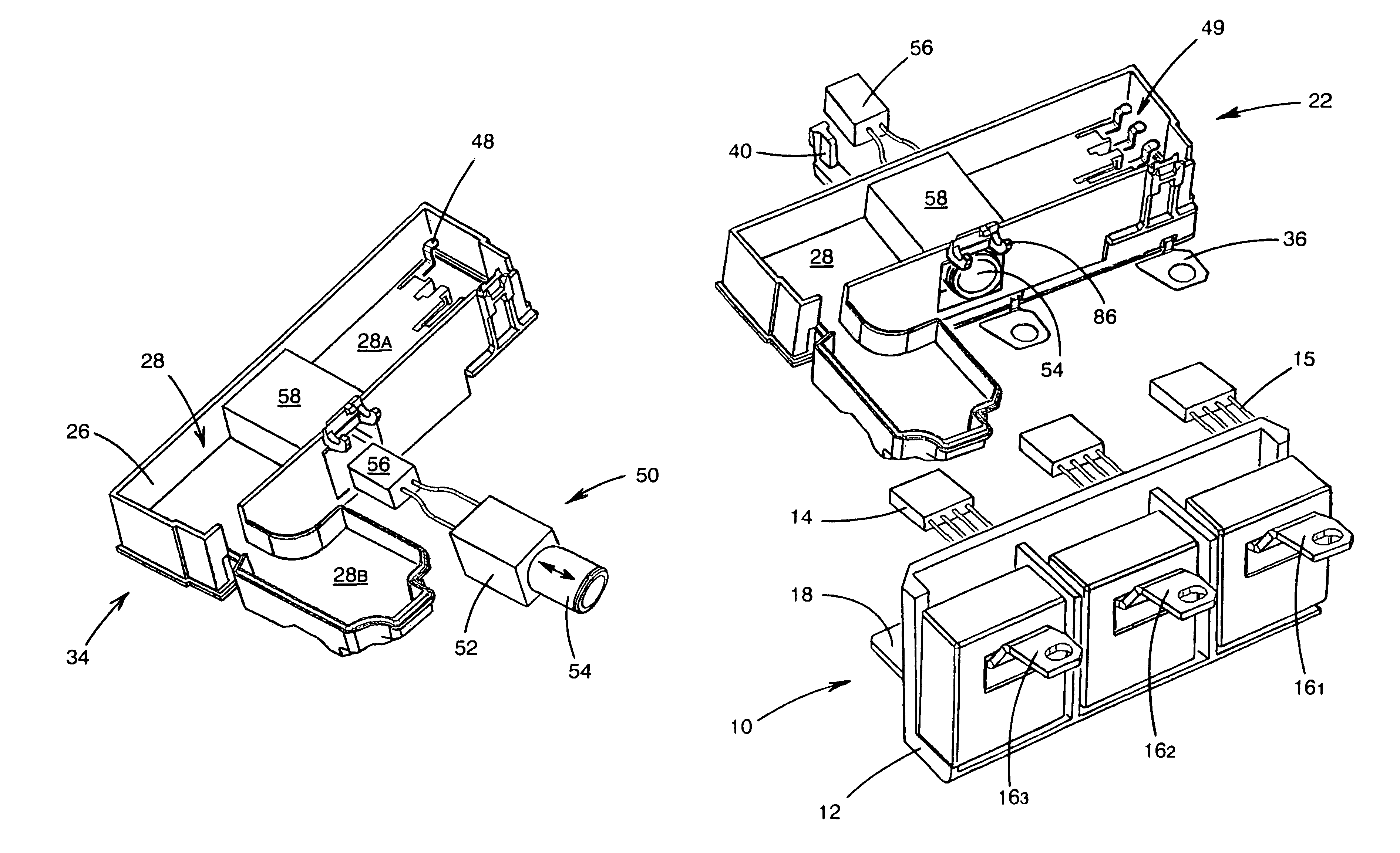
[0008]Among other advantages, the object of the invention is to palliate the shortcomings of existing electronic trip units and to propose a trip device having a design that enables the different component elements necessary for performing the required functionalities to be included. In particular, the trip device according to the invention complies with the space occupation constraints and can replace a trip unit, in particular a magnetic or thermal trip unit, in an existing circuit breaker. Furthermore, the trip device according to the invention integrates both the electromagnetic actuation device of the circuit breaker contacts and measurement and processing of the different values representative of the current flowing in the distribution circuit, and also the means enabling the user to set the tripping threshold parameter values. Assembly thereof is thereby facilitated. In addition, as the architecture is common to the different circuit breakers whatever the number of poles or the breaking intensity of the latter, assembly and storage of the different components are rationalised.
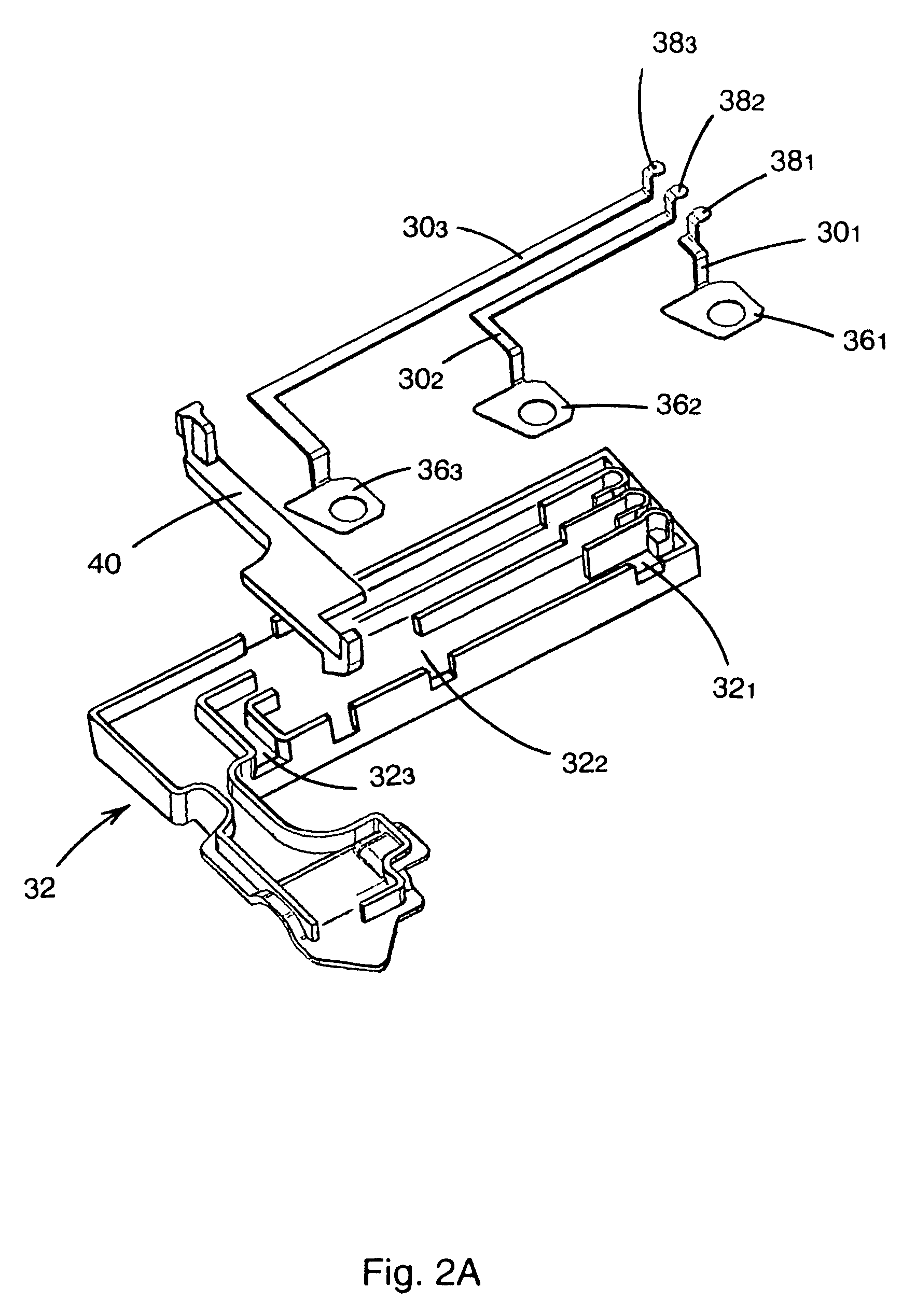
[0012]The electronic module also preferably comprises a printed circuit board in the cavity of the case, a board whereto the connector of the actuator is connected, preferably via the edge thereof, and advantageously by means of a localised connection between the side panels of the cover and the bottom part. The connections with a transformer unit to form an electronic trip device are preferably also made via the edge and between the walls of the bottom part and the cover of the case according to the invention. This solution increases the compactness of the device and prevents any action which might result in incorrect positioning and / or damage to the connecting wires. Said transformer unit and the electronic module are preferably secured to one another by clipping so as to eliminate any screw or other non-captive securing means.
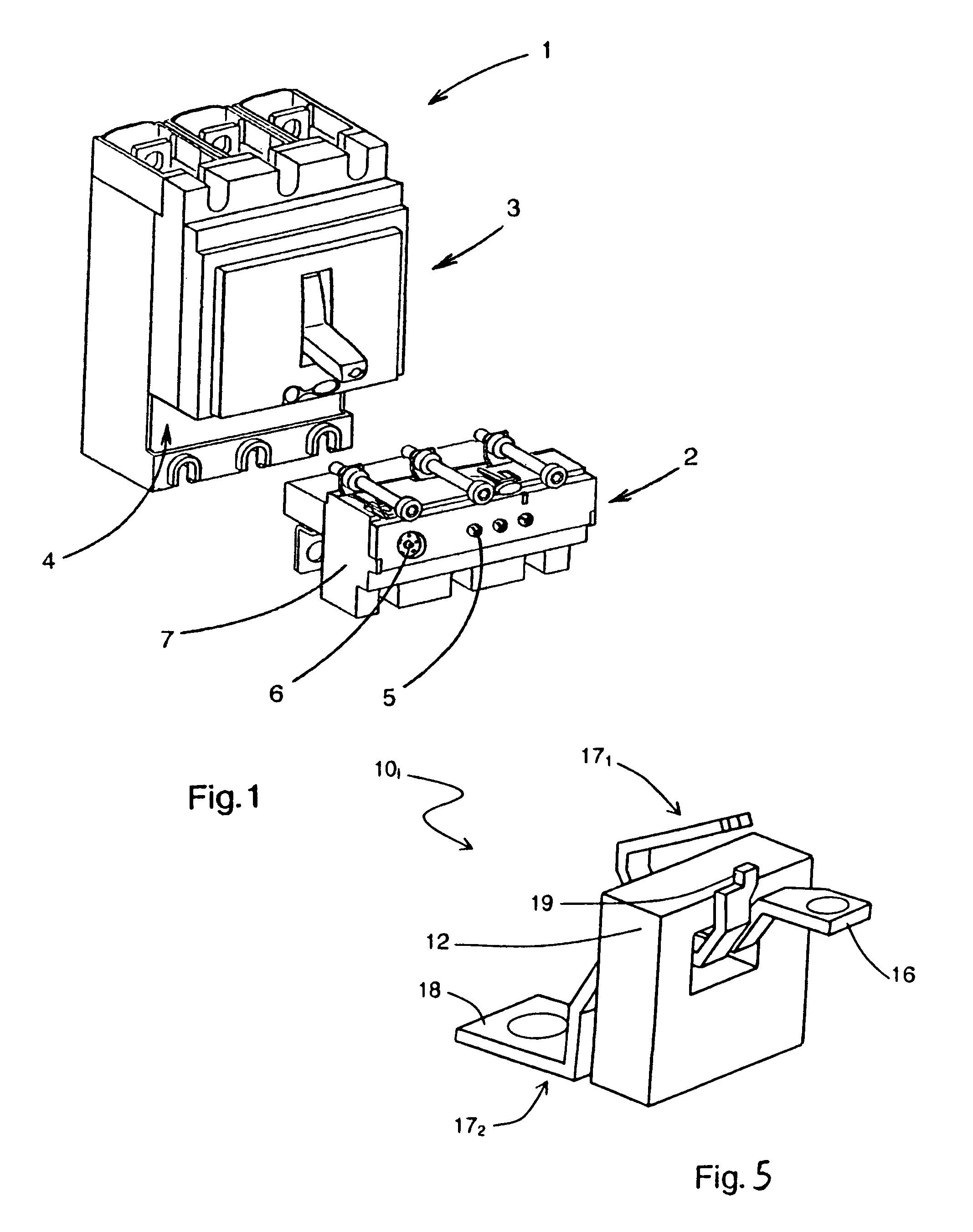
[0016]The case and the electronic module according to the invention are suitable for trip devices of any rating, and for any number of poles, in particular three or four. The trip device can be fitted in the case of a switchgear unit, also an object of the invention, in order to trigger separation of the contacts thereof. For this purpose, the trip device according to a preferred embodiment of the invention is associated with an alignment of breakable screws of the comb connector type so that fitting in a circuit breaker arrangement is achieved by connecting each of the comb connector screws on the connecting strips, tightening, and sectioning of the screws, the residual part whereof remains connected to an assembly of consequent size. This makes for ease of assembly guaranteeing uniformity of the tightening torques.

Problems solved by technology

However, the space requirements inherent to these functionalities cannot be minimized at will, in particular on account of the constraints generated by the connections between the different component elements performing processing, measuring, parameter setting and actuation.
In spite of the various designs, such as for example that described in the document EP 0 991 095, electronic trip devices are therefore not optimised and require connection of auxiliaries, thereby making the circuit breaker assembly procedure more cumbersome.

Method used


Image

  • Electronic trip device case for a circuit breaker, electronic trip device and assembly method thereof
  • Electronic trip device case for a circuit breaker, electronic trip device and assembly method thereof
  • Electronic trip device case for a circuit breaker, electronic trip device and assembly method thereof

Examples


case 20

[0072]Case 20 is thereby designed with additional assembly means for an auxiliary module, in particular a fitting rail 92 on a side panel 26′ of cover 24, for example of dovetail type, so that assembly and disassembly operations of an auxiliary module (not shown) connected thereto are easy while keeping the mechanical strength to resist shocks and vibrations when the clearances are optimised. Securing of the auxiliary module on the trip device can be performed by an element of clip type. Auxiliary module fitting rail 92 is moreover designed to enable an optic connection 90 between main printed circuit board 64 and the module fitted on rail 92, for example a hole in rail 92 on panels 26, 26′ of case 20 operates in conjunction with a diode fitted under board 64, preferably ensuring the tightness of cavity 28A even if no auxiliary module is fitted. Auxiliary module is also provided with a diode facing that of trip device 200 in its fitted position. The two means can exchange their data...


PUM

PropertyMeasurementUnit
angleaaaaaaaaaa
opening angleaaaaaaaaaa
lengthaaaaaaaaaa

Abstract

An electronic module for a trip device has been optimised so as to integrate the known functionalities, in particular threshold parameter setting, current measurements, voltage taps, read-out display and communication. An electromagnetic actuator is further present in the electronic module to optimise breaking of the associated circuit breaker. The space occupation constraints inherent to location of the trip device in existing switchgear units have been respected.

Description

TECHNICAL FIELD[0001]The invention relates to tripping of switchgear apparatuses by means of electronic processing. The invention relates more particularly to an electronic trip device able to be integrated in existing switchgear apparatuses and which acts on the contacts of the latter by means of an integrated electromagnetic actuator. An electronic module of the trip device can further comprise known functionalities, in particular threshold parameter setting, current measurements, test connector, display and communication functions.[0002]The invention also relates to a case for an electronic trip device having a design that has been optimized for maximum compactness. The invention also relates to the trip device and the assembly method thereof which is simplified in spite of the density of integrated functionalities.STATE OF THE ART[0003]As illustrated in the document FR 2 696 275 and represented schematically in FIG. 1, a moulded case circuit breaker 1 comprises a trip device 2 e...

Claims


Application Information

Patent Timeline
Patent Type & Authority Patents(United States)
IPC IPC(8): H01H9/02H01H13/04
CPCH01H71/7409H01H71/125H01H2071/006Y10T29/49105H01H2071/0292Y10T29/4902H01H2071/0242H01H49/00
Inventor BELLOTTO, HENRIBUTTIN, FREDERIC TOTI
Owner SCHNEIDER ELECTRIC IND SAS
Why Eureka
Try Eureka