
Functional separating spacer of the cartridges in a multipole switchgear device and circuit breaker

a multi-pole switchgear device and cartridge technology, applied in the direction of contact, electrical apparatus, contact engagement, etc., can solve the problems of single breaking exceeding the limits of certain electric performances, difficult connection and complex assembly

Active Publication Date: 2014-09-09
SCHNEIDER ELECTRIC IND SAS
View PDF13 Cites 0 Cited by
  • Summary
  • Abstract
  • Description
  • Claims
  • Application Information

AI Technical Summary

Benefits of technology

This invention relates to a new switchgear device that overcomes the shortcomings of existing double enclosure switchgear. It is designed to use standardized parts and modularity to improve performance. The switchgear device is also meant to be durable and compact, with a low-voltage range of up to 630 or 800 amperes. The device features a spacer with a central partition and end parts that securely position power connections between breaking units. The spacer also allows for the simultaneous movement of the breaking units using energy storage means, such as a torsion spring. The invention also includes a sealed element for protecting terminal clamping screws and means to withstand the stresses of the trip device. Overall, this invention shows an improvement in the design and performance of switchgear devices.

Problems solved by technology

However, single breaking reaches its limits for certain electric performances.
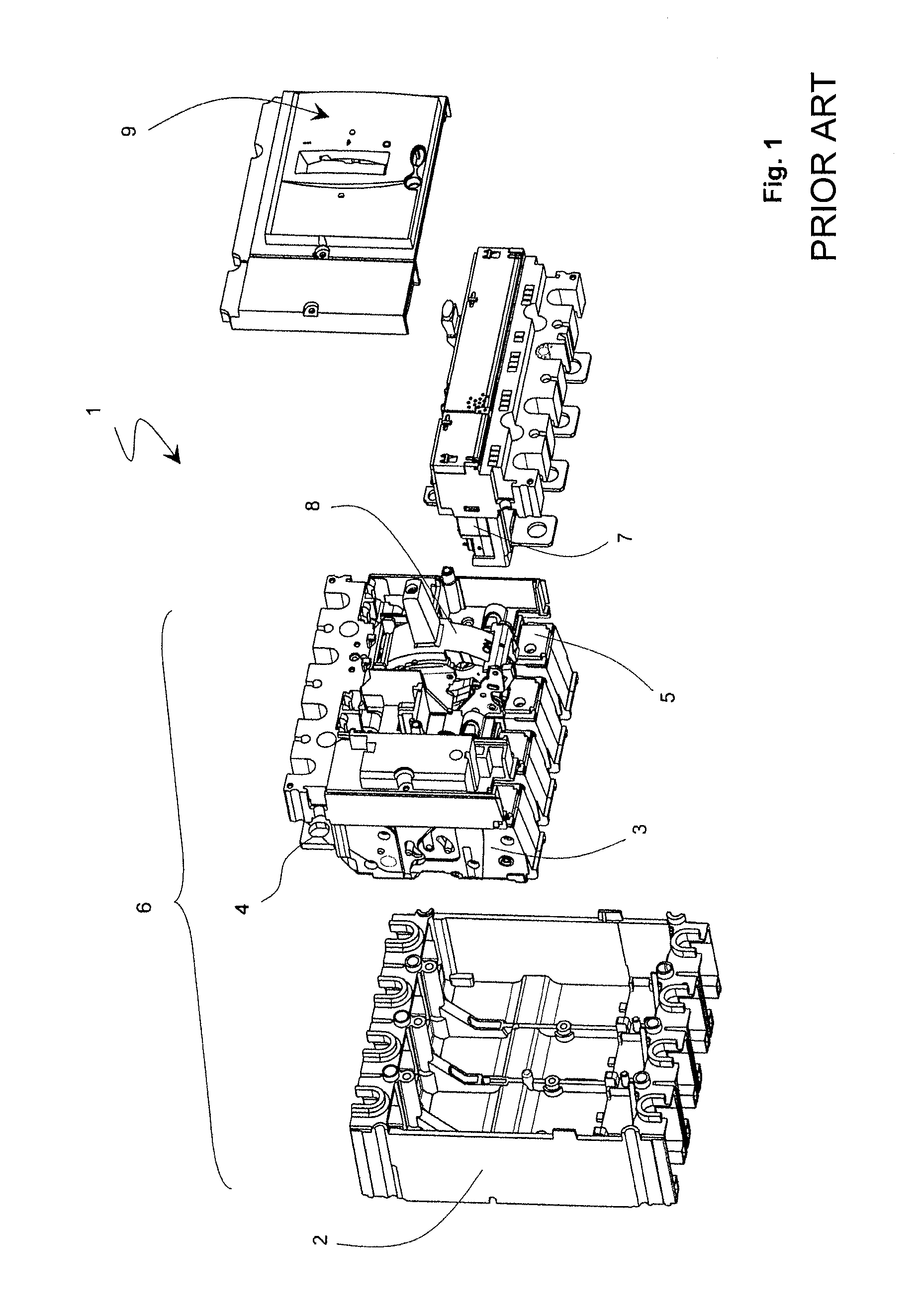
Furthermore, existing rotary double breaking devices are based on insertion via the front of the trip device 7, i.e. via the face comprising the nose 9 and the handle of the circuit breaker 1, which gives rise to difficulties of connection and complex assembly.

Method used


Image

  • Functional separating spacer of the cartridges in a multipole switchgear device and circuit breaker
  • Functional separating spacer of the cartridges in a multipole switchgear device and circuit breaker
  • Functional separating spacer of the cartridges in a multipole switchgear device and circuit breaker

Examples


Embodiment Construction

[0024]With a concern for simplification of presentation of a preferred embodiment of the invention, the elements composing the switchgear apparatus 1, and in particular the single-pole cartridges 3 forming the breaking device 6, will be described in relation with the position of use in which the circuit breaker 1 is fitted in place in a panel, the opposite to FIG. 1, with the nose 9 comprising the vertical handle parallel to the wall or mounting plate, the line-side connection terminal strips 4 on the electric line located at the top and the trip device 7 at the bottom. The use of the relative position terms such as “lateral”, “top”, “bottom”, etc. should not be interpreted as a limiting factor.

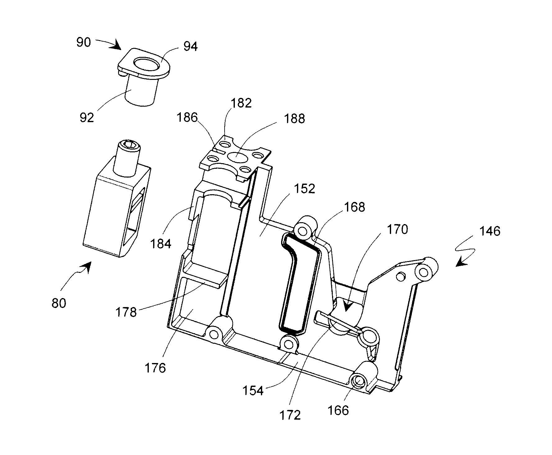
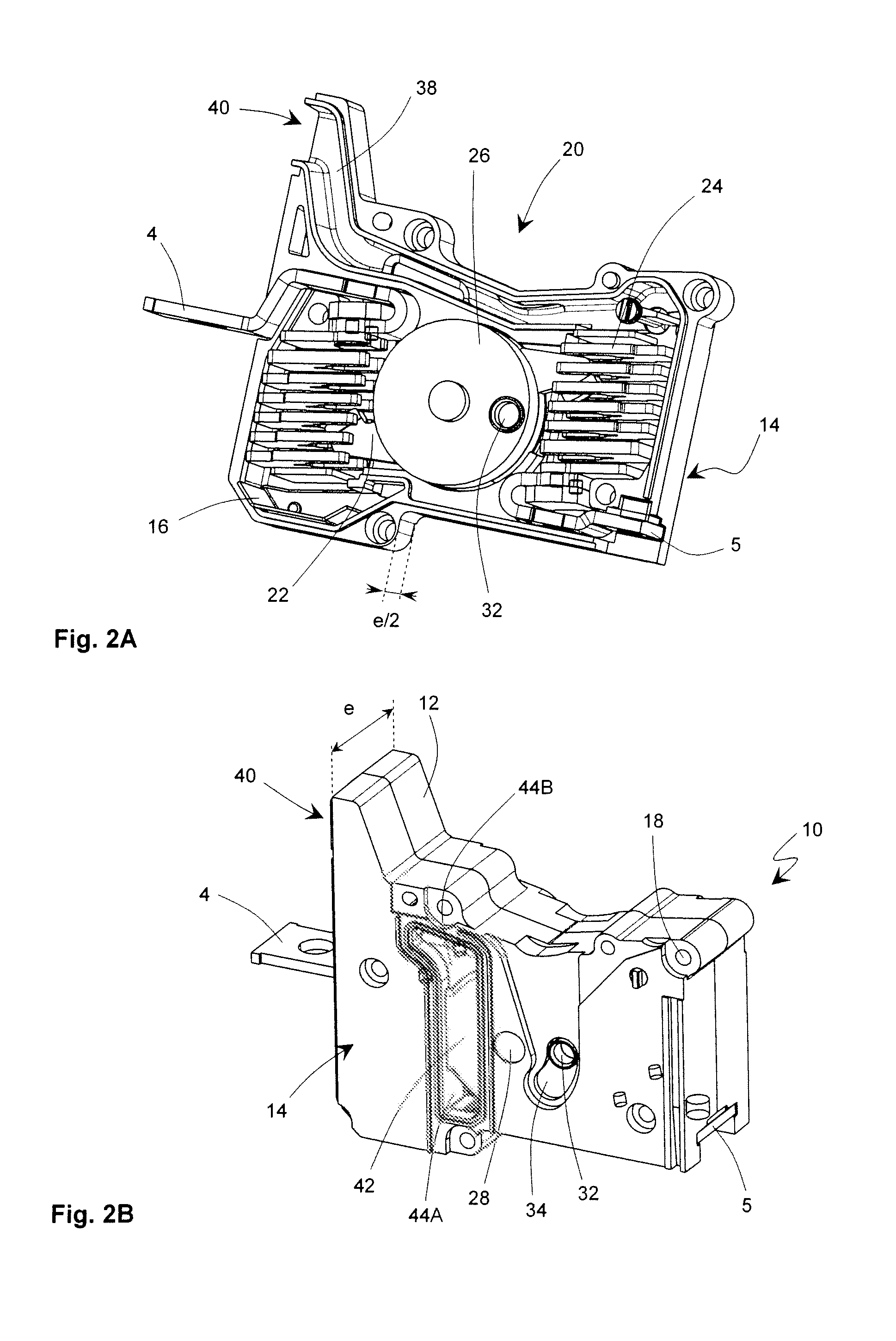
[0025]A multipole switchgear apparatus according to the invention 100, generally a circuit breaker, comprises a trip device 7 associated with a breaking device 600 comprising a plurality of cartridges 10, or single-pole breaking units, each unit 10 performing breaking of a single pole and bei...


PUM


Abstract

In order to take maximum advantage of the modularity provided by a multipole circuit breaker (100) with double enclosure, a new architecture is proposed. A part of the outer case (48) of the switchgear apparatus is formed directly when assembly of the breaking device (600) is performed by juxtaposition and securing between single-pole breaking units (10), spacers (46) and side walls (50). It is thus possible to use the spacers (46) for various functionalities, and in particular to modify the external aspect of the switchgear apparatus (100) or the nature of the trip device in delayed manner.

Description

[0001]This application is a national stage entry of International Application No. PCT / FR2010 / 000594, filed Aug. 30, 2010 designating the U.S., which claims the benefit of French application Ser. No. 09 / 04458, filed Sep. 18, 2009.TECHNICAL FIELD[0002]The invention relates to a modular low-voltage multipole circuit breaker wherein a trip device is common to all the poles which each comprise an independent breaking cartridge. The invention relates to a new architecture for this type of circuit breakers in which the conventional double enclosure is modified to optimize the modularity for different functions and / or sizes to be parameterized in the circuit breaker.STATE OF THE ART[0003]A conventional low-voltage multipole switchgear apparatus 1, generally a circuit breaker, as described in EP 0 542 636 and illustrated in FIG. 1, comprises a double enclosure: an outer case 2 of the circuit breaker 1 houses a plurality of single-pole current breaking units 3 between a line-side terminal str...

Claims


Application Information

Patent Timeline
Patent Type & Authority Patents(United States)
IPC IPC(8): H01H9/26H01H13/72H01H13/76H01H1/20H01H71/02
CPCH01H1/2058H01H2071/0285H01H71/0235
Inventor GRUMEL, CHRISTOPHEANGLADE, HERVERIVAL, MARC
Owner SCHNEIDER ELECTRIC IND SAS
Learn More