
Method and system for measuring strain in twisted cord

a technology of twisted cords and measuring systems, applied in the direction of instruments, force/torque/work measurement apparatus, image enhancement, etc., can solve the problems of twisted cords slipping in one or both of the cord grips, ambiguity in the measurement of the distance between the cord grips, and difficulty in determining the precise point at which the twisted cord transitions

Inactive Publication Date: 2012-07-12
BRIDGESTONE AMERICAS TIRE OPERATIONS LLC
View PDF5 Cites 4 Cited by
  • Summary
  • Abstract
  • Description
  • Claims
  • Application Information

AI Technical Summary

Problems solved by technology

Unfortunately, there are some problems with this testing method.
For example, with many cord grip designs, it can be difficult to determine the precise point at which the twisted cord transitions from being in the cord grip to being between the cord grips.
This can lead to ambiguity in measurements of the distance between the cord grips.
Additionally, the twisted cord can slip in one or both of the cord grips when the strain is applied.
Because the distance between the cord grips is no longer equivalent to the strained length of the twisted cord, the strain measurement is inaccurate.
Moreover, whether any slippage occurred and the amount of slippage is very difficult to determine making the magnitude of the inaccuracy in the strain measurement hard to estimate.
Further, during strain testing at elevated temperatures, expansion of the metal parts in the cord grips can introduce more ambiguity into the strain measurements.
As a result, there can be significant uncertainty regarding the accuracy of the strain measurements using this method.

Method used


Image

  • Method and system for measuring strain in twisted cord
  • Method and system for measuring strain in twisted cord
  • Method and system for measuring strain in twisted cord

Examples


Embodiment Construction

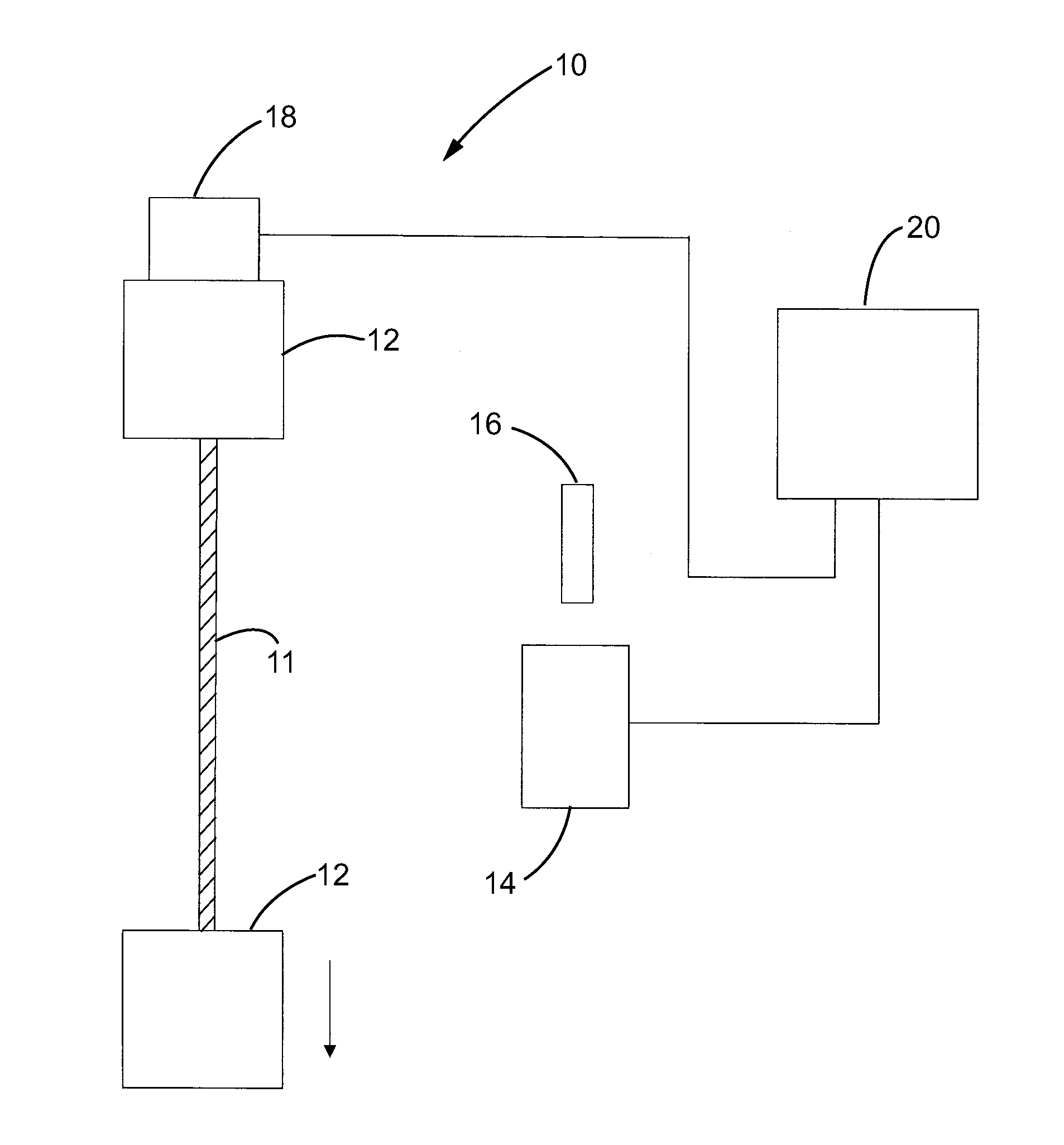
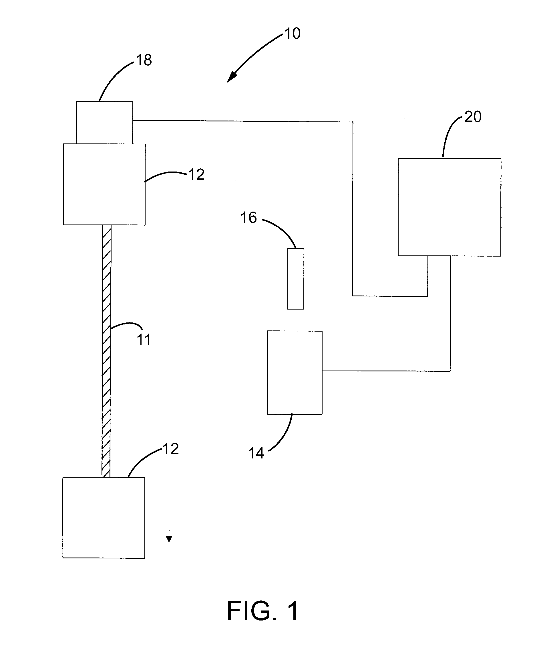
[0005]Referring to FIG. 1 of the drawings, an exemplary embodiment of a strain testing system 10 according to the invention is schematically shown. The illustrated testing system 10 includes a pair of spaced cord grips 12 each of which is configured to grip an end of a twisted cord test specimen 11. The twists in the cord are shown in exaggerated fashion in FIG. 1 for illustrative purposes. In a known manner, at least one of the cord grips 12 is movable relative to the other cord grip 12 in order to apply a tension force on the twisted cord 11. The twisted cord specimen 11 can be any type of twisted cord, however, the invention has particular applicability, and is described in connection with, the testing of polyester, nylon and rayon twisted cords that are used in the casings of vehicle tires. The invention can also be used in the testing of twisted steel cords used in the belts of vehicle tires.

[0006]In order to determine the strain on the twisted cord test specimen 11 that result...


PUM


Abstract

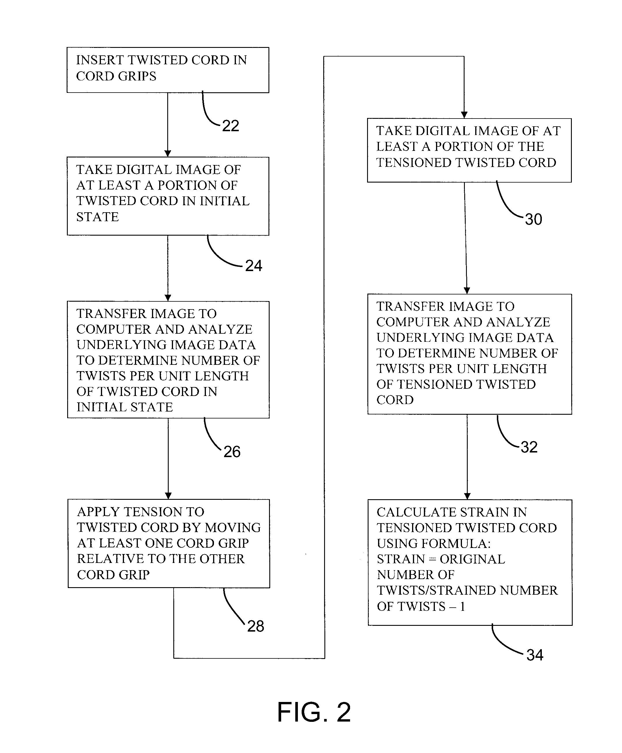
A method for measuring strain in a twisted cord is provided. The method includes the step of securing the ends of the twisted cord in respective cord grips in an initial state and taking a first digital image of at least a portion of the twisted cord in the unloaded state. Image data of the first image is analyzed to determine the number of twists per unit length in the first digital image. A load is applied to the twisted cord. A second digital image of at least a portion of the loaded twisted cord is then taken. The image data of the second image is analyzed to determine the number of twists per unit length in the second digital image. A parameter of the tensioned twisted cord is calculated using the number of twists per unit length in first digital image and the number of twists per unit length in the second digital image.

Description

BACKGROUND OF THE INVENTION[0001]Twisted cords are a component used in the main body, or casing, of motor vehicle tires. In particular, tire casings incorporates fabrics of polyester, nylon or rayon cords with in the casing rubber compound. These cords are commonly twisted to improve their strength. As part of the tire design and manufacturing process, these cords are subject to various tests to determine their properties under different operating conditions. One common test determines the strain on the twisted cords under various conditions. Such strain tests are commonly performed using a test rig that includes a pair of cord grips at least one of which is movable relative to the other. To perform a test, an end of twisted cord test specimen in placed in each of the cord grips and then the at least one cord grip is moved relative to the other in order to apply a force, or tension, on the twisted cord.[0002]During these tests, the strain on the twisted cord is measured as the chang...

Claims


Application Information

Patent Timeline
IPC IPC(8): G01N3/08H04N7/18G06F19/00
CPCG01N3/068G01N3/08G06T2207/30124G01N2203/0647G06T7/001G01N3/26
Inventor ZAKELJ, PAUL
Owner BRIDGESTONE AMERICAS TIRE OPERATIONS LLC
Learn More