Separate ethernet forwarding and control plane systems and methods with interior gateway route reflector for a link state routing system

Active Publication Date: 2012-08-02
CIENA
View PDF10 Cites 16 Cited by
  • Summary
  • Abstract
  • Description
  • Claims
  • Application Information

AI Technical Summary

Benefits of technology

[0004]In an exemplary embodiment, a network includes a plurality of interconnected switches; a plurality of Provider Edge (PE) routers interconnected via the plurality of interconnected switches; one or more Distributed Link State Interior Gateway Route Reflectors interconnected to the PE routers; a control plane comprising the PE routers and the one or more Interior Gateway Route Reflectors; and a forwarding plane between the PE routers over the plurality of interconnected switches. In this description, the phrase “Link State Interior Gateway Route Reflectors” is equivalent to “Interior Gateway Route Reflectors” or IGRR. Optionally, the one or more Interior Gateway Route Reflectors include a single server disposed at one of the plurality of interconnected switches, and wherein each of the plurality of PE routers is communicatively coupled to the single server through the plurality of interconnected switches. Alternatively, the one or more Interior Gateway Route Reflectors include a plurality of geographically diverse servers, and wherein each of the PE routers is communicatively coupled to one of the plurality of geographically diverse servers. The forwarding plane may utilize traffic engineered Ethernet over Shortest Path Bridging-Media Access Control (SPBM). The plurality of geographically diverse servers are configured to appear as a single designated peering node to the plurality of PE routers. A logical layer two network server-server interconnect extends a messaging fabric between the geographically diverse servers to create the single designated peering node. At each of the PE routers, the forwarding plane appears as various interconnects through the plurality of interconnected switches, and wherein, at each of the PE routers, the control plane appears as interconnects to the one or more Interior Gateway Route Reflectors. The forwarding plane is logically separated from the control plane. The plurality of interconnected switches and the one or more Interior Gateway Route Reflectors replace functionality associated with a Provider router suc

Problems solved by technology

Disadvantageously, the requirement for direct adjacency poses scaling challenges.
However, the DR still po

Method used


Image

  • Separate ethernet forwarding and control plane systems and methods with interior gateway route reflector for a link state routing system
  • Separate ethernet forwarding and control plane systems and methods with interior gateway route reflector for a link state routing system
  • Separate ethernet forwarding and control plane systems and methods with interior gateway route reflector for a link state routing system

Examples


Embodiment Construction

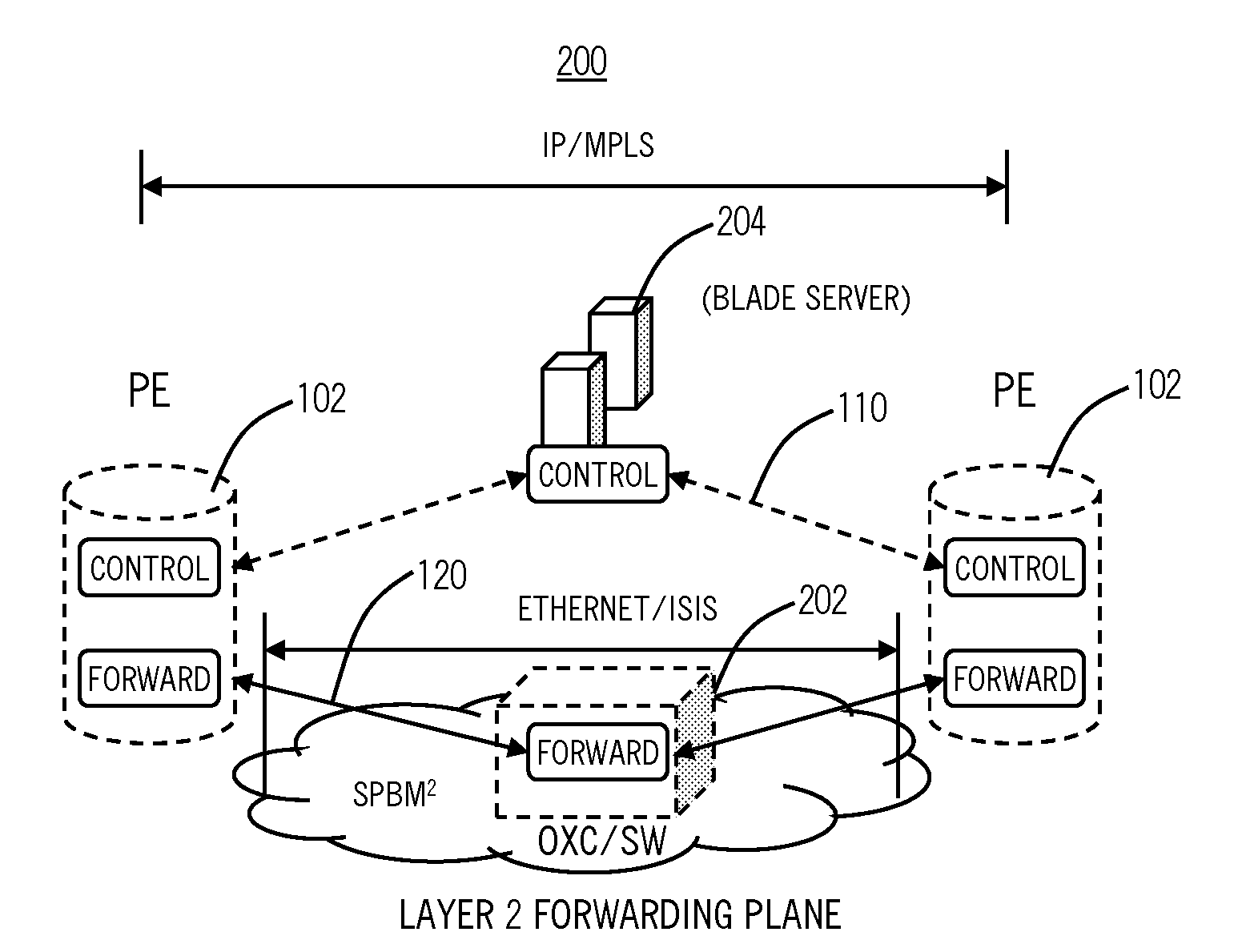
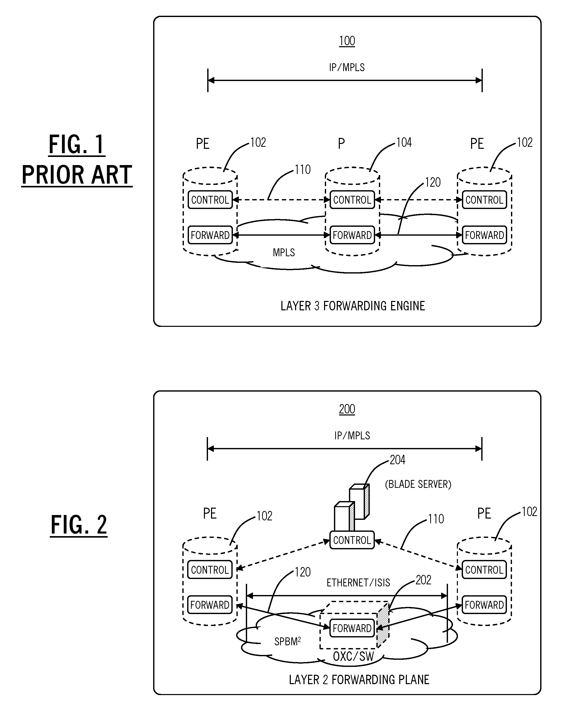
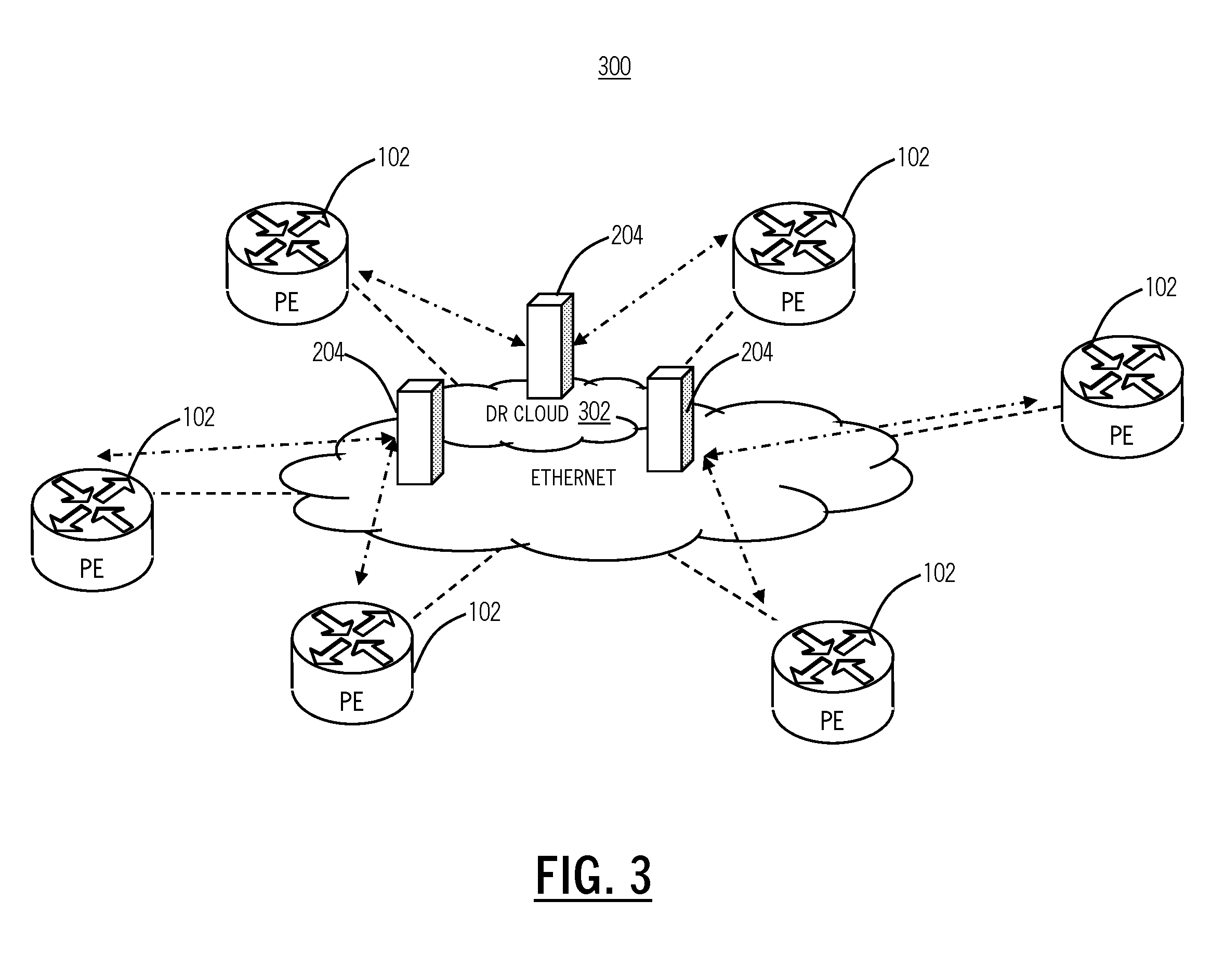
[0018]In various exemplary embodiments, the present invention provides a separate Ethernet forwarding and control plane system, method, network, and architecture with a distributed Interior Gateway route reflector for the control plane system and a layer two network architecture for the forwarding system. The present invention utilizes a cloud implementation for the DR reducing peering requirements on individual components and distributing the functionality. The use of an Interior Gateway Route Reflector (via the special treatment of the “pseudo-node” and “designated router” mechanisms inherent in IS-IS and OSPF) enables a layer two cloud (SPB-M, SPB-V, Virtual Private LAN Service (VPLS), conventional IEEE 802.1) to provide scalable and robust connectivity within a routed network. The distribution of this entity improves robustness and scalability. Through the architecture of the present invention, the P router is eliminated and is replaced by layer two switches and servers. Such an...


PUM


Abstract

The present disclosure provides a separate Ethernet forwarding and control plane system, method, network, and architecture with a Link State Interior Gateway route reflector for the control plan system and a layer two network architecture for the forwarding system. The present invention optionally utilizes a cloud implementation for the Designated Router (DR) or designated peering node reducing peering requirements and distributing the functionality. Through the architecture of the present invention, the Provider router is obviated by the application of layer two switches and servers. Such an architecture provides improved scaling, performance, and cost reduction.

Description

FIELD OF THE INVENTION[0001]The present invention relates generally to networking. More particularly, the present invention relates to a separate Ethernet forwarding and control plane system, method, network, and architecture with an Interior Gateway route reflector associated with a Link State Routing System, such as Open Shortest Path First (OSPF) or Intermediate System to Intermediate System (IS-IS), for the control plane system, and a layer two network architecture for the forwarding system.BACKGROUND OF THE INVENTION[0002]In Multi-Protocol Label Switching (MPLS), a P router or Provider Router is a Label Switch Router (LSR) that functions as a transit router of the core network. The P router typically connected to one or more Provider Edge (PE) routers. In conventional embodiments, P routers and PE routers each operate a control plane and a forwarding plane and each of the routers forms a direct adjacency with every other router to which it is directly attached at the IP layer. ...

Claims


Application Information

Patent Timeline
IPC IPC(8): H04L12/56
CPCH04L45/50H04L45/04
Inventor BRAGG, NIGEL L.DUNCAN, IAN H.
Owner CIENA
Why Eureka
Try Eureka