
Network architecture for remote robot with interchangeable tools

a robot and network architecture technology, applied in the field of remote robot control, can solve the problems of adversely affecting the use of the pipe, robots that are not designed to be flexible, self-configurable, easy to operate, etc., and achieve the effect of less time-critical decisions and a slow feedback loop

Active Publication Date: 2006-04-06
REDZONE ROBOTICS
View PDF27 Cites 205 Cited by
  • Summary
  • Abstract
  • Description
  • Claims
  • Application Information

AI Technical Summary

Benefits of technology

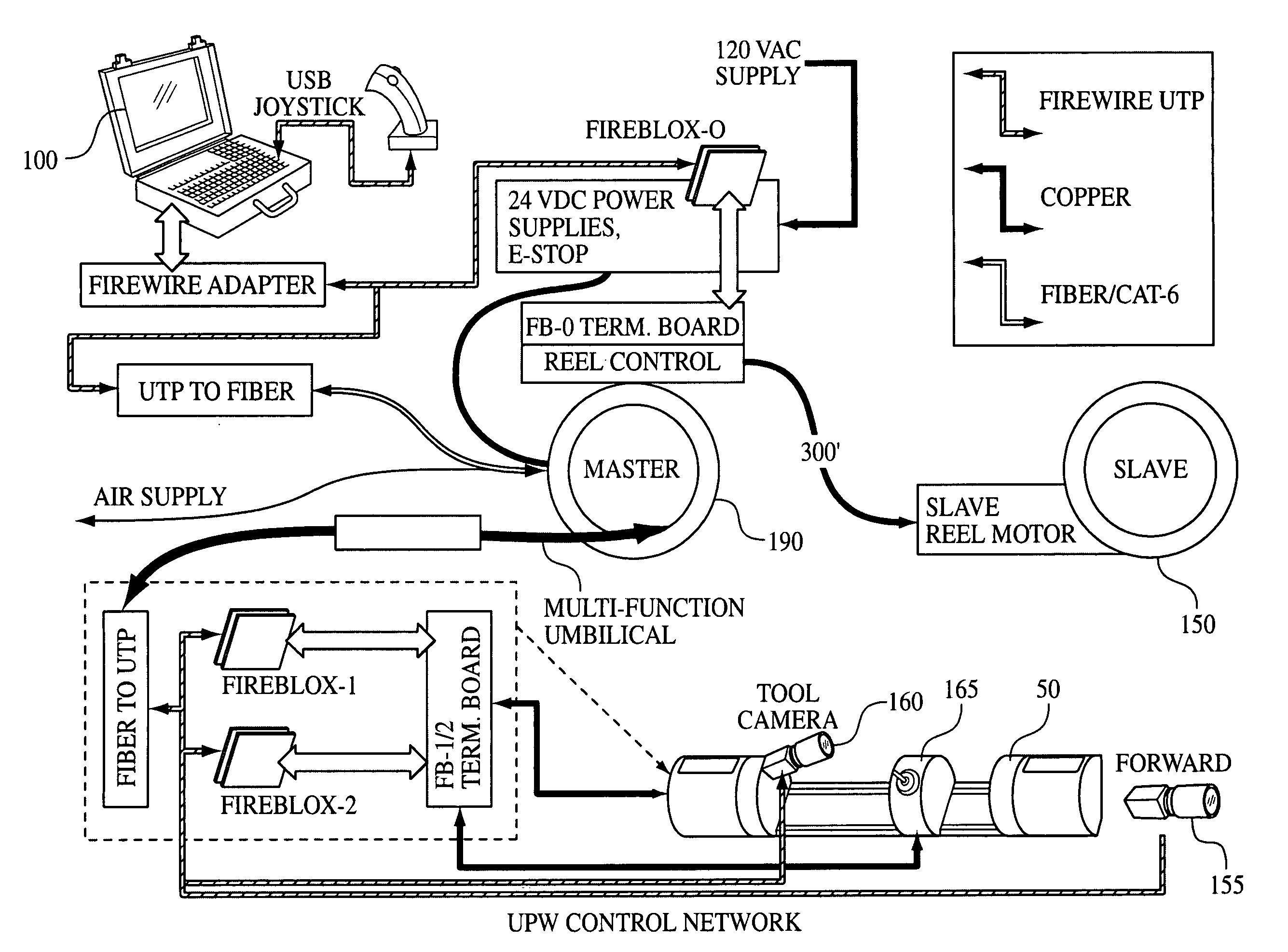
[0019] The robot and attachment (tool head or sensor) typically include a first level of local digital feedback that provides a quick feedback response for certain time-sensitive signaling decisions. The robot is also communicatively connected to a remote computer (for example a computer at the surface when a robot is exploring subterranean pipes) for a slightly

Problems solved by technology

Such custom-designed machines are very expensive to build and maintain, and do not take advantage of the similarities between the various tasks that need to be performed.
In short, most robotic applications are special purpose, and these robots are not designed to be flexible, self-configurable, and easy to operate.
After years of wear, the walls of the pipelines begin to crack, leak and generally deteriorate, and this wear may adversely affect use of the pipe.
In either case, the conventional method lacks a great deal of precision.
However, these prior robotic application do not present a universal architecture and robotic device that can be used to perform these, and other similar tasks using a robot with interchangeable tool heads.
These prior art systems do not include self-recognizing components connected to the network architecture.
Finally, these prior systems do not include a Graphical User Interface (“GUI”) that builds itself based upon the recognition of robotic components and robotic functionality.
In fact, conventional interfaces are nothing more than analog overlays and are not GUIs at all.

Method used


Image

  • Network architecture for remote robot with interchangeable tools
  • Network architecture for remote robot with interchangeable tools
  • Network architecture for remote robot with interchangeable tools

Examples


Embodiment Construction

[0034] It is to be understood that the figures and descriptions of the present invention have been simplified to illustrate elements that are relevant for a clear understanding of the invention, while eliminating, for purposes of clarity, other elements that may be well known. Those of ordinary skill in the art will recognize that other elements are desirable and / or required in order to implement the present invention. However, because such elements are well known in the art, and because they do not facilitate a better understanding of the present invention, a discussion of such elements is not provided herein. The detailed description will be provided hereinbelow with reference to the attached drawings.

[0035] The present invention is generally directed to a network architecture for controlling robotic devices, wherein the robotic device includes a universal interface for attaching a variety of different tool heads and sensors (collectively “attachments”) thereto. It should be note...


PUM


Abstract

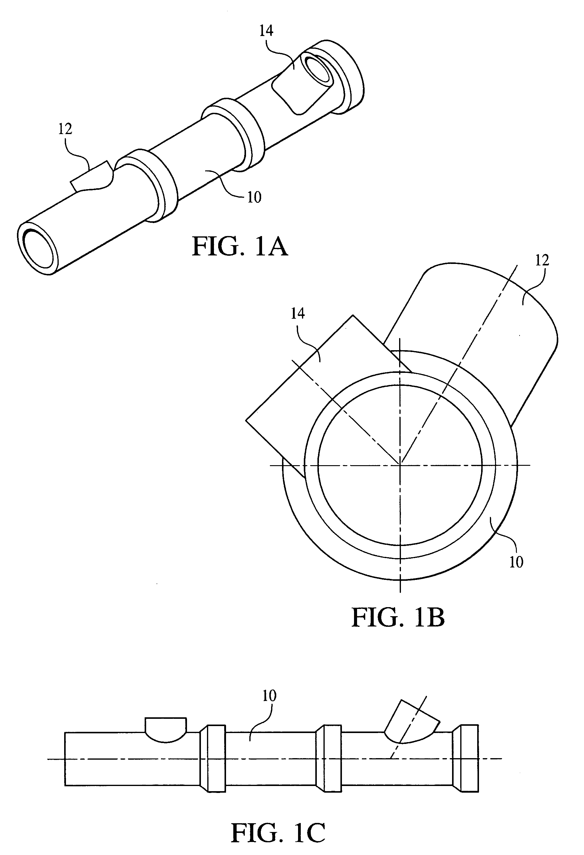
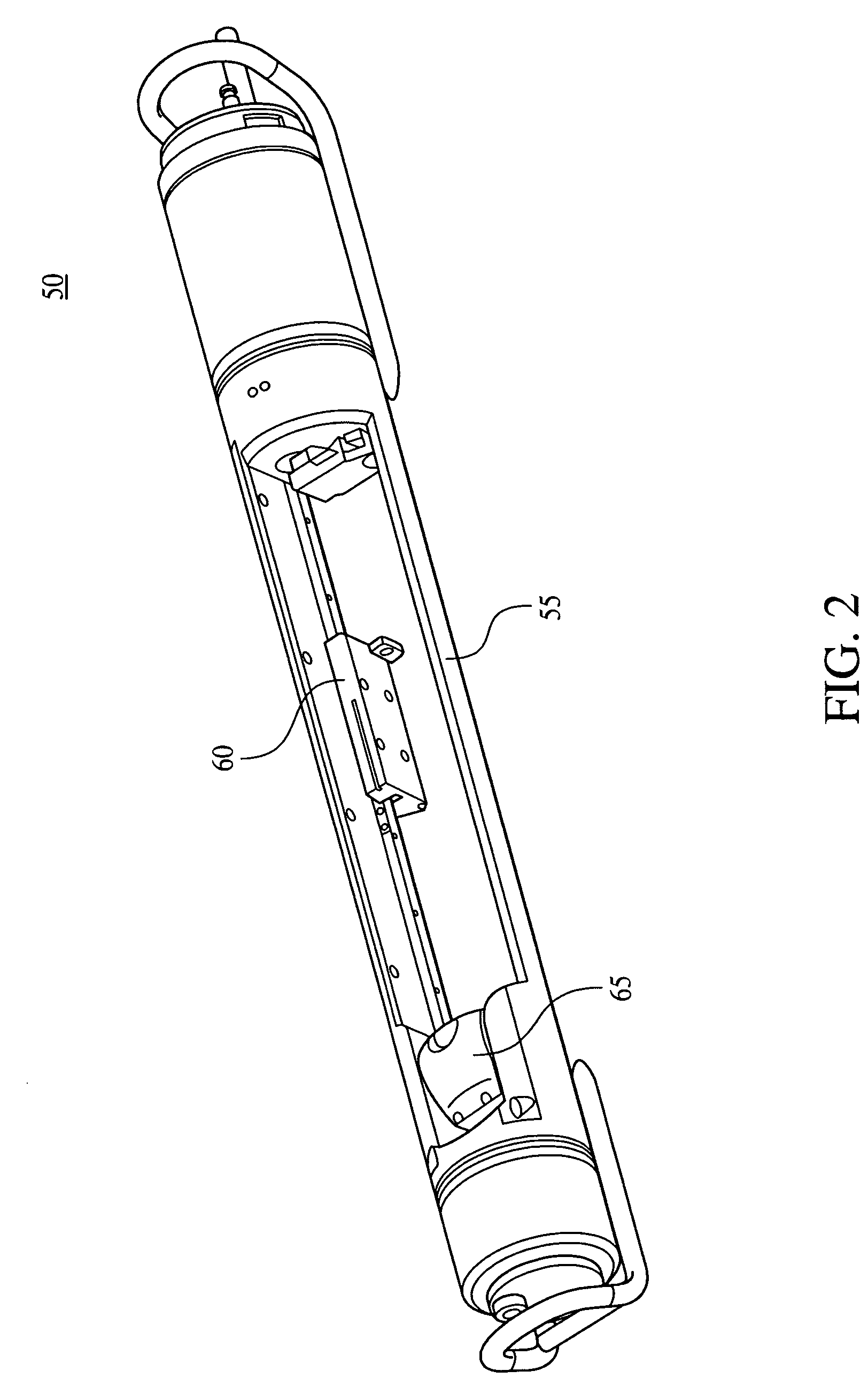
Systems, methods and devices for the remote control of a robot which incorporates interchangeable tool heads. Although applicable to many different industries, the core structure of the system includes a robot with a tool head interface for mechanically, electrically and operatively interconnecting a plurality of interchangeable tool heads to perform various work functions. The robot and tool head may include several levels of digital feedback (local, remote and wide area) depending on the application. The systems include a single umbilical cord to send power, air, and communications signals between the robot and a remote computer. Additionally, all communication (including video) is preferably sent in a digital format. Finally, a GUI running on the remote computer automatically queries and identifies all of the various devices on the network and automatically configures its user options to parallel the installed devices. Systems according to the preferred embodiments find particular application in the pipeline arts. For example, interchangeable tool heads may be designed to facilitate inspection, debris clearing, cleaning, relining, lateral cutting after relining, mapping, and various other common pipeline-related tasks.

Description

BACKGROUND OF THE INVENTION [0001] 1. Field of the Invention [0002] The present invention relates generally to systems, devices and methods related to the remote control of robots, and, more specifically, the present invention relates to a system architecture utilizing a robot with interchangeable tools used for pipeline rehabilitation. [0003] 2. Description of the Background [0004] The use of robotic devices or robots to perform tasks that are either too difficult, too dangerous, or too repetitive in order to gain efficiencies over similar manual processes is well known in many arts. These robots are typically either tele-operated (an operator acting on visual cues or visual servo feedback), operator assisted, forced multiplication (one operator overseeing a plurality of robots) or autonomous (no human intervention). [0005] In most of these industries, specific robots have been custom-designed to perform each individual task that is automated. Such custom-designed machines are very...

Claims


Application Information

Patent Timeline
IPC IPC(8): G06F19/00
CPCB25J9/1617G05B2219/33189G05B2219/33192G05B2219/40099G05B2219/45233
Inventor CLOSE, ERICSLIFKO, ADAMHUDSON, EDISON T.GENISE, RONALD G.
Owner REDZONE ROBOTICS
Learn More