RF transmitter with digital feedback for MRI

a transmitter and digital technology, applied in the field of rf transmit system, can solve the problems of inability to inability to accurately achieve the desired amplitude and phase of the transmit signal, and inability to stabilize the feedback loop, etc., to achieve easy and reliable manner, reduce safety margin, and improve susceptibility/sensitivity to patient movements

Inactive Publication Date: 2010-06-10
KONINKLIJKE PHILIPS ELECTRONICS NV
View PDF18 Cites 29 Cited by
  • Summary
  • Abstract
  • Description
  • Claims
  • Application Information

AI Technical Summary

Benefits of technology

[0015]One advantage of the method and RF transmit system according to the invention is that by the realization in the digital domain, instabilities of the feedback loop can be avoided in a relatively easy and reliable manner even under detrimental or changing load conditions, if e.g. in case of an MRI system, an examination object is moved within the examination space which is exposed to the RF excitation field. In particular, also changes are taken into account of the load condition that are caused by motion of the patient such as breathing motion.
[0016]The safety margin can be reduced significantly, if a real-time feedback loop is used to change the input signal of the RF amplifier accordingly with the desired RF demand or in case current sources would be used. Therefore, during t

Problems solved by technology

It has revealed, that a disadvantage of the above method and arrangement is that instabilities of the feedback loop can occur under certain circumstances and load conditions, and that the expense for the circuitry increases rapidly with an increasing number of transmitting coils to be controlled.
Furthermore, due to noise and component tolerances, with such a feedback loop only a limited accuracy of the desired amplitude and phase of the transmit signals can be obtained.
These variations cause RF pulse output changes commonly known as pulse overshoot and drop.
These effects cause that the RF field generated may de

Method used


Image

  • RF transmitter with digital feedback for MRI
  • RF transmitter with digital feedback for MRI
  • RF transmitter with digital feedback for MRI

Examples


first embodiment

[0033]According to the invention, the RF transmit system generally comprises an RF power amplifier for feeding an RF transmitter with an RF signal, an activation circuit to provide an input signal to the RF power amplifier, and a control circuit to control the activation circuit. The control circuit samples the output signal of the RF power amplifier (or of the RF transmitter), digitally compares the measured output signal with a prescribed demand signal and digitally corrects the input or demand signal to the RF power amplifier.

[0034]According to a preferred variation of this first embodiment, the control circuit has a feedforward function, which presets the activation circuit on the basis of a selected MRI acquisition sequence.

[0035]By the first embodiment, especially an improved transmit level stability and linearity can be achieved. Furthermore, wider variations of the RF power level can be achieved by advance setting to the amplification level of the RF power amplifier. By the ...

second embodiment

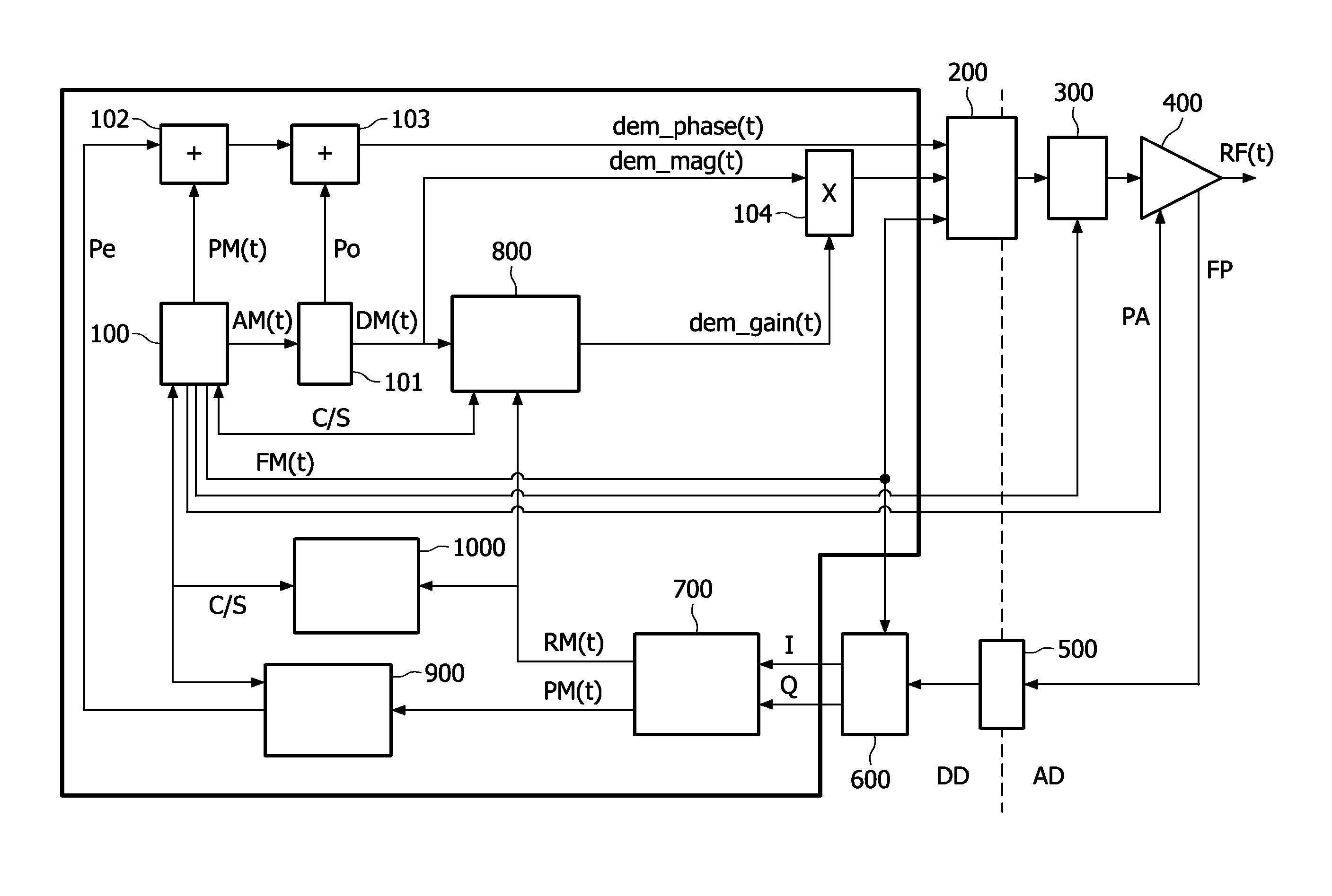
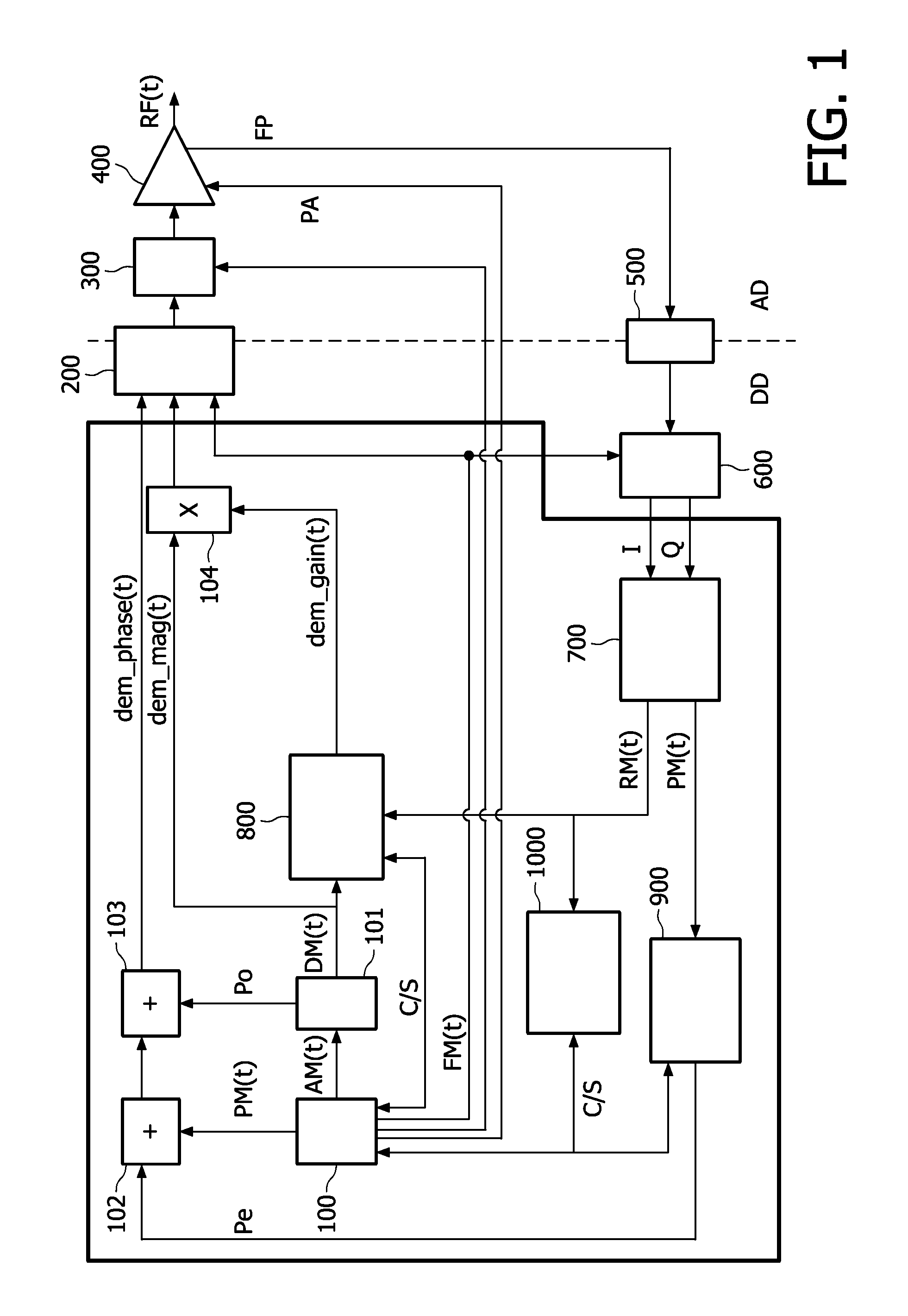
[0070]FIG. 4 shows a functional block diagram of an RF transmit system according to the invention in the form of a one-channel RF transmit system. A multi-channel RF transmit system can be realized by a plurality of such channels. The RF transmit system comprises an RF waveform generator 10 for generating in the digital domain a demand RF signal, which is fed to a complex gain predistorter 11 and an adaption unit 17. An output of the complex gain predistorter 11 is connected with an input of a digital-to-analog converter 12 for converting the input signal into the analog domain. The analog output signal is then fed via an RF power amplifier 13 to an RF transmitter 14, which for example comprises an RF coil.

[0071]The RF transmit signal is sensed by means of a sensor for example in the form of a small coil which is positioned at the RF transmitter 14 and / or at the output of the power amplifier 13. One of these sensor signals (schematically indicated by a combination of the sensor sign...

third embodiment

[0081]FIG. 5 shows a functional block diagram of an RF transmit system according to the invention, again in the form of a one-channel RF transmit system. A multi-channel RF transmit system can again be realized by a plurality of such channels.

[0082]The same or corresponding components as indicated in FIG. 4 are denoted with the same reference numerals.

[0083]This RF transmit system again comprises an RF waveform generator 10 for generating a demand RF transmit signal in the digital domain, which is fed to a complex gain predistorter 11 and to an adaption unit 17. The output of the complex gain predistorter 11 is connected with an input of a digital-to-analog converter 12 for converting the input signal into the analog domain. The output of the digital-to-analog converter 12 is connected with the input of a quadrature modulator 19, the output signal of which is fed via an RF power amplifier 13 to an RF transmitter 14 e.g. in the form of an RF coil.

[0084]The RF transmit signal is again...


PUM


Abstract

A method and an RF transmit system for generating RF transmit signals for feeding an RF transmitter (14) in the form of, or comprising, one or more antenna device(s), coil(s), coil elements, or coil array(s) is disclosed. Furthermore, a multi-channel RF transmit system for feeding a plurality of such RF transmitters, especially for use as an RF excitation system in a magnetic resonance imaging (MRI) system for exciting nuclear magnetic resonances (NMR) is disclosed. A demand RF transmit signal is compared in the digital domain with an RF transmit signal and digitally corrected with respect to differences or errors between both by means of a complex predistorter (11), an adaption unit (17) and a look-up table unit (18).

Description

FIELD OF INVENTION[0001]The invention relates to a method and an RF transmit system for generating RF transmit signals for feeding an RF transmitter in the form of, or comprising, one or more antenna device(s), coil(s), coil elements, or coil array(s). Furthermore, the invention relates to a multi-channel RF transmit system for feeding a plurality of such RF transmitters, especially for use as an RF excitation system in a magnetic resonance imaging (MRI) system for exciting nuclear magnetic resonances (NMR). The invention further relates to an MRI system comprising such a one- or multi-channel RF transmit or excitation system.BACKGROUND OF THE INVENTION[0002]WO 2005 / 083458 discloses a “method of effecting nuclear magnetic resonance experiments using Cartesian feedback”, and a particular arrangement with a plurality of transmitting coils, wherein each transmitting coil having its own independent transmitter and current detector for setting the amplitude and phase of its current to it...

Claims


Application Information

Patent Timeline
IPC IPC(8): G01R33/44
CPCG01R33/3607
Inventor GRAESSLIN, INGMARVERNICKEL, PETERDEN BOEF, JOHANNES HENDRIK
Owner KONINKLIJKE PHILIPS ELECTRONICS NV
Why Eureka
Try Eureka