Method for controlling a wind energy plant

a technology of wind energy and control method, which is applied in the direction of propellers, emergency control, motors, etc., can solve the problems of reducing the aerodynamic power capture of the rotor in the rest position, the desired value of the blade adjustment deviating from the measured actual value, and the error is put out. , to achieve the effect of simple and reliable manner

Active Publication Date: 2009-03-26
NORDEX ENERGY SE & CO KG
View PDF5 Cites 40 Cited by
  • Summary
  • Abstract
  • Description
  • Claims
  • Application Information

AI Technical Summary

Benefits of technology

[0019]The nacelle can be rotated into the rest position by an azimuth drive of the wind energy plant, i e. by motor action, in a particularly simple and reliable manner. In this it may be provided that the nacelle is only rotated into the rest position when the azimuth drive is in the production operation. In particular, an automatic rotation of the nacelle into the rest position is not possible in the service mode of the azimuth drive.

Problems solved by technology

An error has to be detected in the case, for instance, that a desired value of the blade adjustment deviates from a measured actual value of the blade adjustment in a critical degree.
When this limit difference is exceeded, an error is put out.
When the blade adjustment equipment has furthermore a redundancy system, it may be provided that an error is put out only when a corresponding error has been recognised for the redundancy system also.
Thus, the aerodynamic power capture of the rotor is reduced in the rest position, by diminishing the effective rotor surface with respect to the wind direction.
For triggering the rotation of the nacelle into the rest position, it may then be sufficient that the adjustment equipment has an error for at least one blade.

Method used


Image

  • Method for controlling a wind energy plant
  • Method for controlling a wind energy plant

Examples


Embodiment Construction

[0025]While this invention may be embodied in many different forms, there are described in detail herein a specific preferred embodiment of the invention. This description is an exemplification of the principles of the invention and is not intended to limit the invention to the particular embodiment illustrated

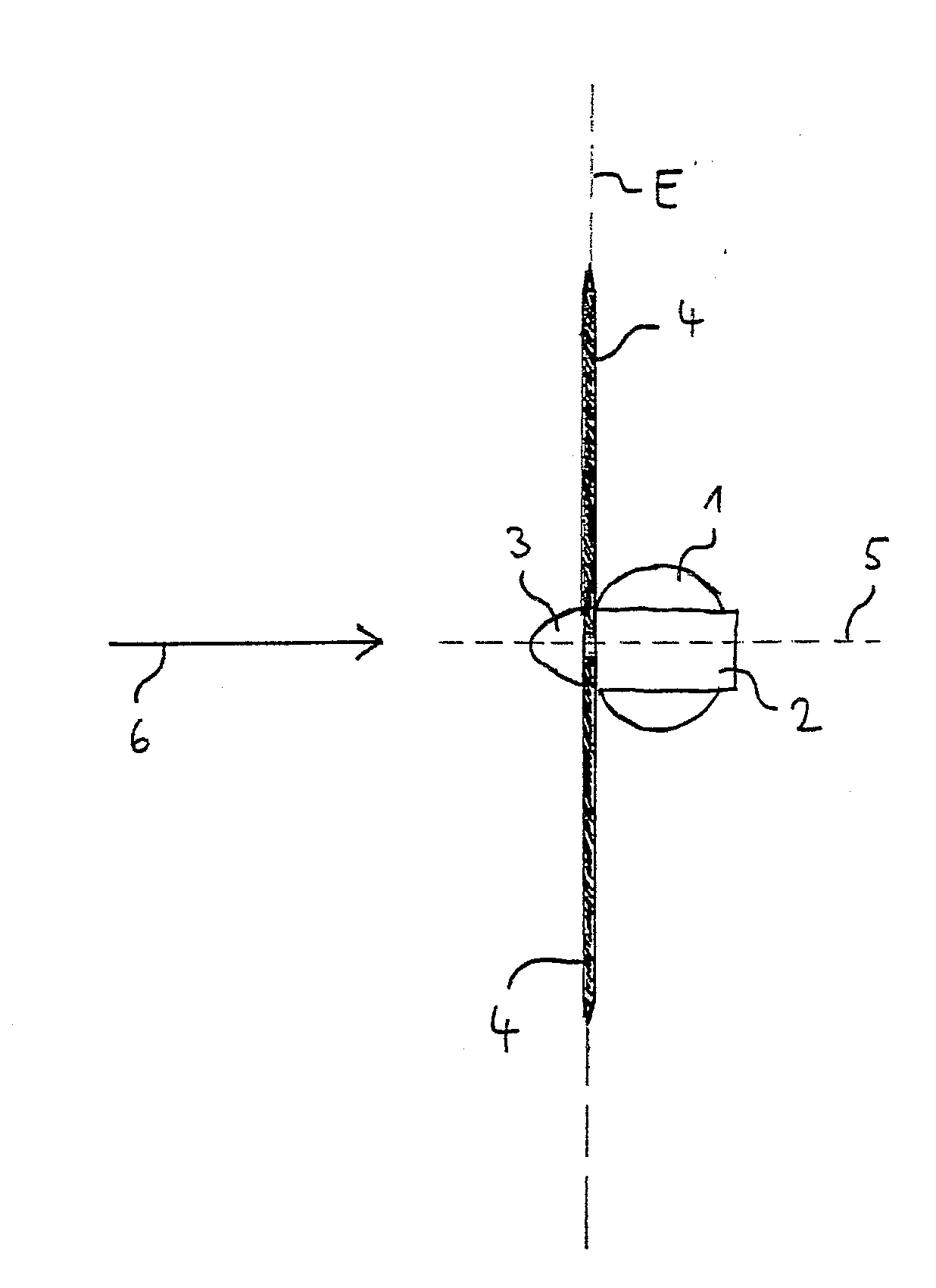
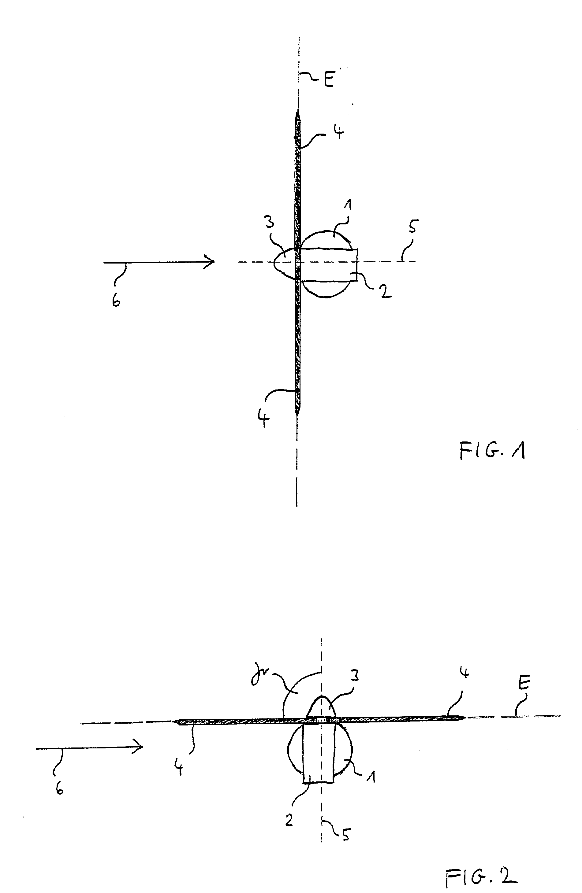
[0026]In the figures, the same reference signs designate the same objects. In the figures, a wind energy plant with a nacelle 2 arranged on a tower 1 is depicted. In the nacelle 2, a rotor 3 with three rotor blades 4 is installed, which are depicted only very schematically in the shown example. The blade adjustment angle of the rotor blades 4 can be adjusted and controlled by a blade adjustment equipment (pitch control) which is not shown in more detail. In this, an own blade adjustment equipment is assigned to each rotor blade 4.

[0027]In the depicted example, the rotor blades 4 are substantially arranged in a plane E. In their rotation around the rotor axis, they extend a cir...


PUM


Abstract

The present invention is related to a method for controlling a wind energy plant, with a nacelle disposed on a tower and with a rotor with at least one rotor blade, the blade adjustment angle of which can be adjusted by means of a blade adjustment equipment. The objective to provide a reduction of the loads acting on the plant when there is a malfunction of the blade adjustment equipment is resolved according to the present invention in that the function of the blade adjustment equipment is monitored, and when an error of the blade adjustment equipment occurs, the nacelle is rotated from an operating position into a rest position, in which there is a flow of the wind against the surface extended by the at least one rotor blade (4) in a rotation of the rotor which is reduced with respect to the operating position.

Description

CROSS-REFERENCE TO RELATED APPLICATIONS[0001]Not applicable.STATEMENT REGARDING FEDERALLY SPONSORED RESEARCH[0002]Not applicable.BACKGROUND OF THE INVENTION[0003]The present invention is related to a method for controlling a wind energy plant, with a nacelle disposed on a tower and with a rotor with at least one rotor blade, the blade adjustment angle of which can be adjusted by means of a blade adjustment equipment, in which the nacelle is rotated around the tower axis.[0004]Wind energy plants in which the blade adjustment angle (also called pitch angle) is adjusted, i.e. the angle of the rotor blade with respect to the rotor plane, are known since a long time. By means of a blade adjustment equipment, the blade adjustment angle can be adjusted depending on the wind velocity acting on the blade (also called pitch adjustment). Thus, at a blade adjustment angle of 90°, there is a minimum power conversion of the wind into mechanical energy, whereas at 0°, maximum power conversion take...

Claims


Application Information

Patent Timeline
Patent Type & Authority Applications(United States)
IPC IPC(8): F03D7/02
CPCF03D7/0212F03D7/0268Y02E10/723F05B2270/107F05B2270/321F05B2270/1011Y02E10/72
Inventor FRESE, THOMASHOSE, GERDWIESE-MULLER, LARS-ULRICH
Owner NORDEX ENERGY SE & CO KG
Why Eureka
Try Eureka