Method for determining photographic environment and imaging apparatus

a technology of imaging apparatus and photographic environment, applied in the direction of color signal processing circuit, color television details, television system, etc., can solve the problems of color flicker, image quality is considerably degraded, and color flicker is noticeable at a high shutter speed, and achieve the effect of easy determination

Inactive Publication Date: 2005-05-05
SONY CORP
View PDF7 Cites 47 Cited by
  • Summary
  • Abstract
  • Description
  • Claims
  • Application Information

AI Technical Summary

Benefits of technology

[0070] Accordingly, it is an object of the present invention to provide a method for determining a photographic environment of an XY-address-scanning imaging apparatus, such as a CMOS imaging apparatus, which ensures that it can be easily determined whether or not photographing is conducted under fluorescent light and, if photographing is conducted under fluorescent light, whether the frequency of fluorescent-lamp driving power supply is 50 Hz or 60 Hz.
[0075] According to the present invention, therefore, when an object is photographed by an XY-address-scanning imaging apparatus such as a CMOS imaging apparatus, it can be determined whether or not photographing is conducted under fluorescent light, and, if under fluorescent light, it can further be determined whether the frequency of the fluorescent-lamp driving power supply is 50 Hz or 60 Hz, in a simple and reliable manner.

Problems solved by technology

Such a change in hue and difference in fluctuation component between colors cause so-called color flicker.
Although FIGS. 3 and 4 show only fluctuation in brightness caused by flicker, actually, changes in color also occur, as described above, and the image quality is considerably degraded.
In particular, color flicker is noticeable at a high shutter speed (or at a short exposure time).
In the CMOS imaging apparatus, color flicker affects the screen, and degradation in image quality becomes more noticeable.
Therefore, the imaging apparatus must be large and expensive.
However, the method disclosed in Japanese Unexamined Patent Application Publication No. 2001-111887 or No. 2002-84466 does not overcome the problem of one-screen flicker shown in FIGS. 5B and 5D or 6B and 6D in which flicker in each screen has the same fringe pattern.
In this case, it cannot be determined that photographing is conducted under fluorescent light.
This method also has a problem, however.

Method used


Image

  • Method for determining photographic environment and imaging apparatus
  • Method for determining photographic environment and imaging apparatus
  • Method for determining photographic environment and imaging apparatus

Examples


Embodiment Construction

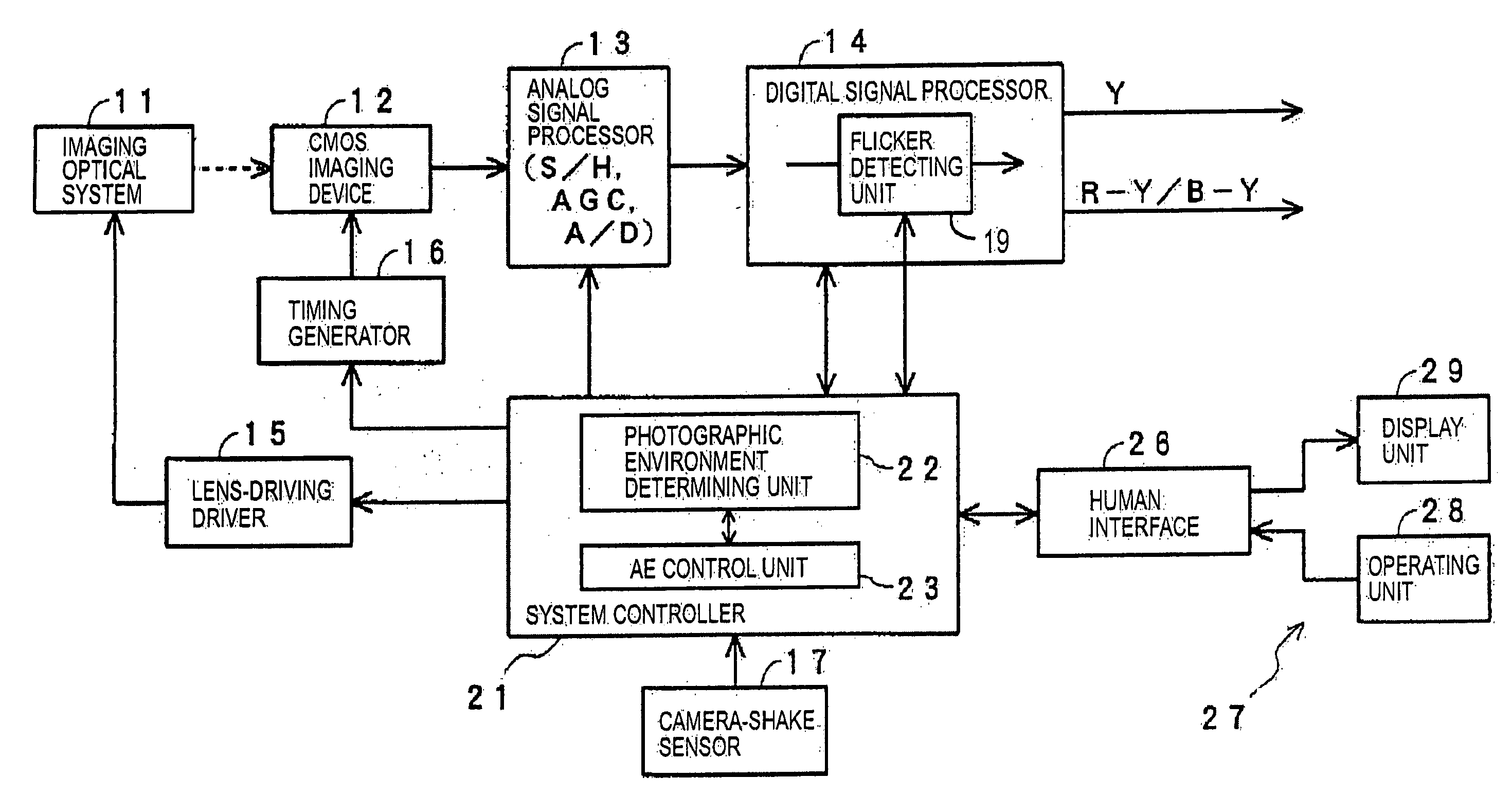
[0099]FIG. 8 is a block diagram showing the system configuration of an imaging apparatus according to the present invention. The imaging apparatus includes an XY-address-scanning imaging device, namely, a CMOS imaging device 12.

[0100] In this imaging apparatus, light from an object is directed into the CMOS imaging device 12 via an imaging optical system 11. The directed light is photoelectrically converted by the CMOS imaging device 12 into an analog video signal composed of primary color signals of R (red), G (green), and B (blue) or complementary color signals.

[0101] The CMOS imaging device 12 includes a two-dimensional array of a plurality of pixels on a CMOS substrate, each pixel having a photodiode (photogate), a transfer gate (shutter transistor), a switching transistor (address transistor), an amplifier transistor, a reset transistor (reset gate), and so on. The CMOS imaging device 12 also includes a vertical scanning circuit, a horizontal scanning circuit, and a video sig...


PUM


Abstract

In an NTSC imaging apparatus, the shutter speed is set to a first value other than N / 120 second, and a flicker detecting process is performed on a video signal obtained at the first shutter speed to extract a particular frequency component. If the level of this frequency component is higher than a threshold value, it is determined that photographing is conducted under fluorescent light with a power supply frequency of 50 Hz. If it is not higher than the threshold value, the shutter speed is set to a second value other than N / 100 second, and a flicker detecting process is performed on a video signal obtained at the second shutter speed to extract a particular frequency component. If the level of this frequency component is higher than a threshold value, it is determined that photographing is conducted under fluorescent light with a power supply frequency of 60 Hz.

Description

BACKGROUND OF THE INVENTION [0001] 1. Field of the Invention [0002] The present invention relates to a method for determining a photographic environment when an object is photographed by an imaging apparatus including an XY-address-scanning imaging device such as a complementary metal oxide semiconductor (CMOS) imaging device. The present invention further relates to an imaging apparatus that determines a photographic environment. [0003] 2. Description of the Related Art [0004] When an object is photographed by an imaging apparatus such as a digital video camera or a digital still camera, when particularly motion pictures are taken, it is important whether or not photographing is conducted under fluorescent light. Fluorescent lamps cause flickering, and therefore, measures against fluorescent flickering need be taken. [0005] When an object is photographed by an imaging apparatus under fluorescent lamps that are powered directly by a household AC power supply, a temporal fluctuation ...

Claims


Application Information

Patent Timeline
Patent Type & Authority Applications(United States)
IPC IPC(8): H04N5/235H04N5/335H04N5/351H04N5/357H04N5/374
CPCH04N5/2357H04N5/2353H04N23/745H04N23/73H04N23/81H04N23/76
Inventor KINOSHITA, MASAYA
Owner SONY CORP
Why Eureka
Try Eureka