Horn antenna device and step-shaped signal feed-in apparatus thereof

a step-shaped signal and antenna device technology, which is applied in the direction of waveguide horns, antenna earthing switches, antennas, etc., can solve the problems of insufficient stability, complex and time-consuming design of waveguide apparatus structures, and difficult determination of resonating modes of electromagnetic waves, so as to achieve easy determination, correct assembly with ease, and the effect of extending the band width of the horn antenna device of the invention

Active Publication Date: 2015-01-29
FINETEK CO LTD
View PDF6 Cites 219 Cited by
  • Summary
  • Abstract
  • Description
  • Claims
  • Application Information

AI Technical Summary

Benefits of technology

[0011]An objective of the invention is to provide a horn antenna device and a step-shaped signal feed-in apparatus thereof. The resonating modes of the horn antenna device of the invention can be easily determined and the horn antenna device can be correctly assembled with ease. The band width of the horn antenna device of the invention is extended.
[0034]The resonating modes of the horn antenna device of the invention can be easily determined and designed according to dielectric of air and the step-shaped signal feed-in apparatus. The stairs are directly connected to the connecting pin, such that high frequency signals can be accurately sent from the connecting pin to the stairs. The stability of the horn antenna device is improved.
[0035]In addition, the directivity of the horn antenna device of the invention is improved. In a radiation pattern of the invention, a width of a main lobe becomes narrower and energy of side lobes is decreased, such that the signal-to-noise rate (SNR) is increased.

Problems solved by technology

As such, the resonating modes, such as TE mode and TM mode, of the electromagnetic waves are difficult to be determined.
Correspondingly, it is complicated and highly time-consuming to design the structures of the waveguide apparatus 90.
Assembling problems, such as the feed-in connector 93 not exactly mounted in the hole 912 and the medium convertor 92 not securely mounted to the body 91, result in inadequate stability.
A radiation pattern of the medium convertor 92 is easily affected and thus lowers the signal quality.

Method used


Image

  • Horn antenna device and step-shaped signal feed-in apparatus thereof
  • Horn antenna device and step-shaped signal feed-in apparatus thereof
  • Horn antenna device and step-shaped signal feed-in apparatus thereof

Examples


Embodiment Construction

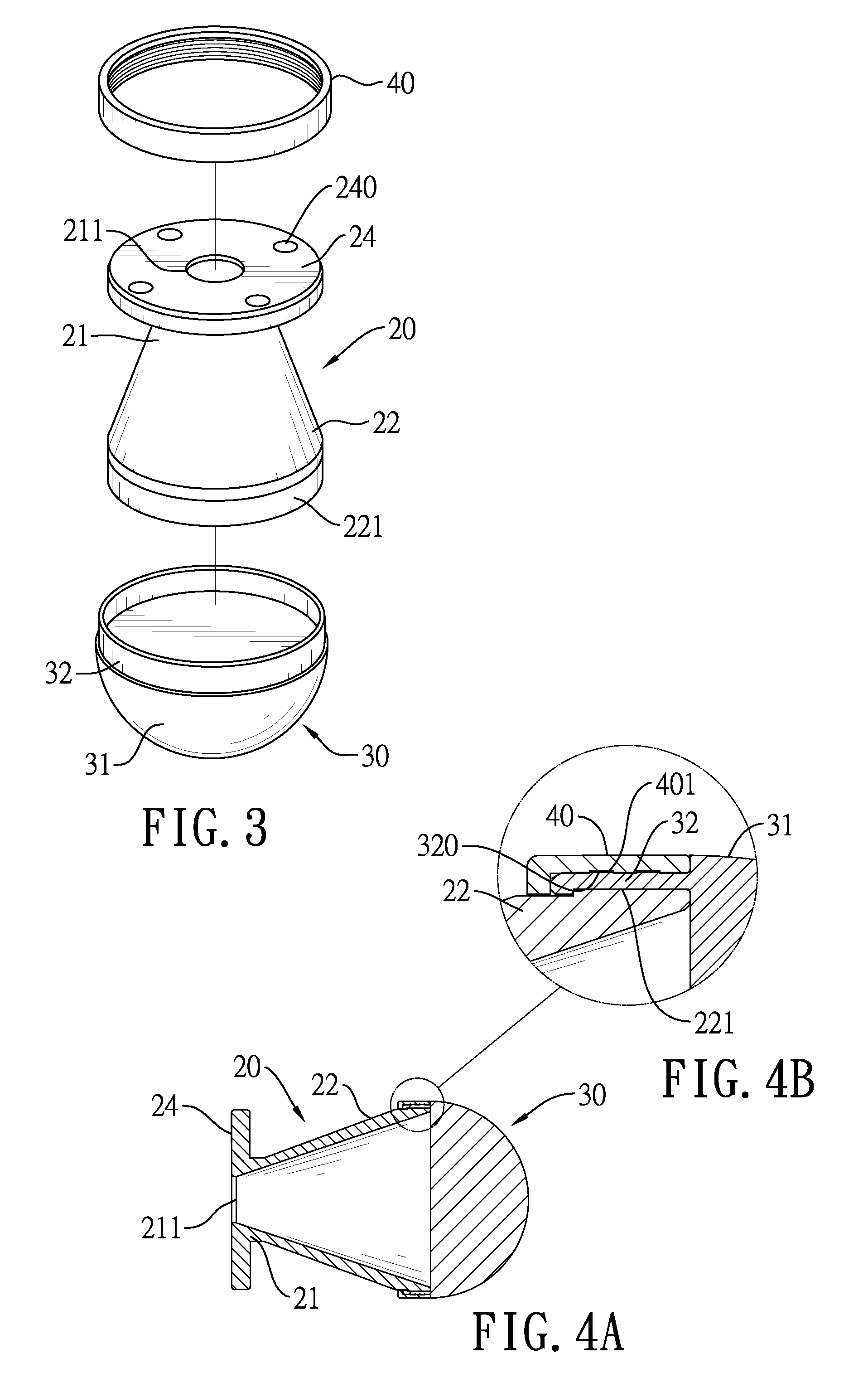
[0047]The horn antenna device of the invention comprises a step-shaped signal feed-in apparatus and a conical horn antenna, or further comprises a lens antenna.

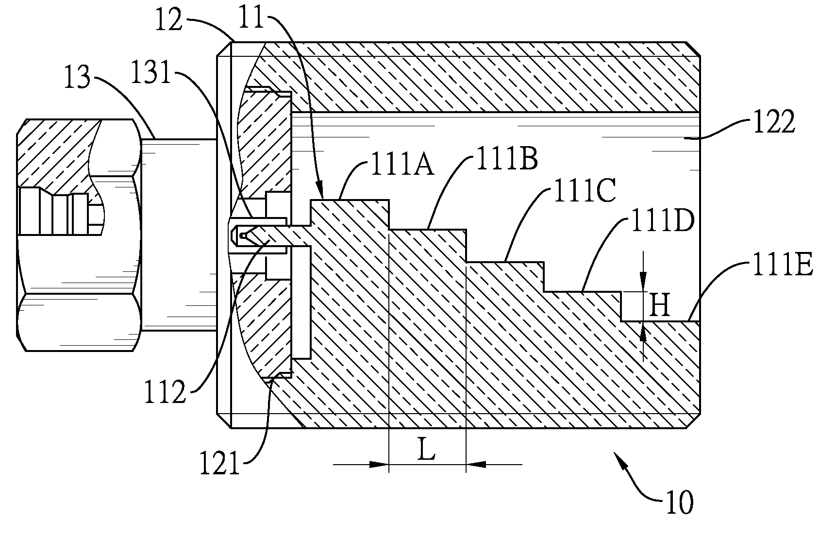
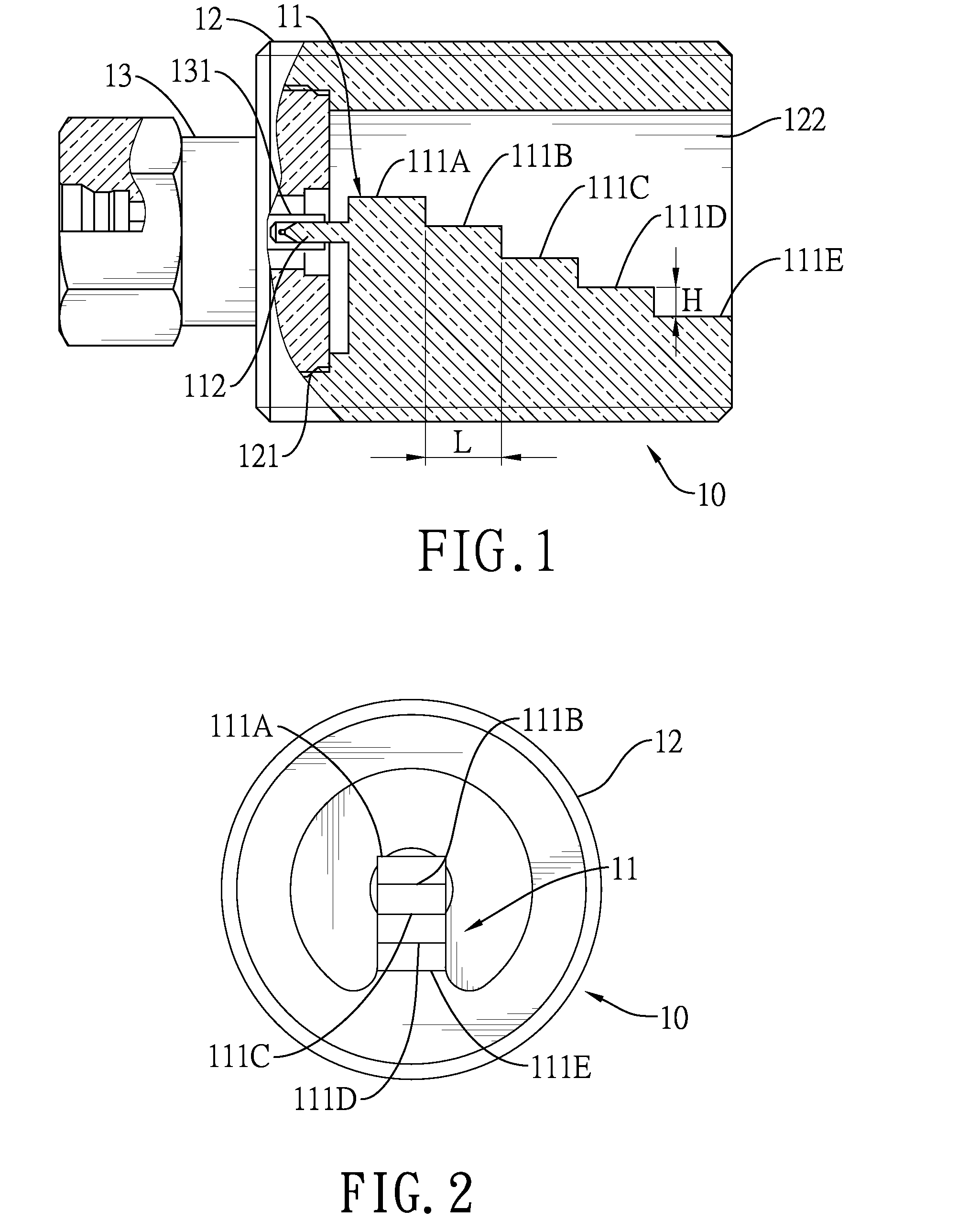
[0048]With reference to FIGS. 1 and 2, a first embodiment of the step-shaped signal feed-in apparatus of the invention is disclosed. The step-shaped signal feed-in apparatus 10 comprises a stepped body 11, a fixture base 12 and a head 13.

[0049]The fixture base 12 is a hollow cylinder and has a connector 121, a space 122, a first end and a second end distal to the first end. The connector 121 is formed in the first end of the fixture base 12.

[0050]The stepped body 11 is mounted in the fixture base 12 and has multiple stairs including a first stair 111A, a second stair 111B, a third stair 111C, a fourth stair 111D, a fifth stair 111E and a connecting pin 112. The stairs 111A-111E are sequentially formed along an axial direction of the fixture base 12. The first stair 111A is the highest stair and is near the first end of the fi...


PUM


Abstract

The present invention relates to a horn antenna device. The horn antenna device has a step-shaped signal feed-in apparatus and a conical horn antenna. The step-shaped signal feed-in apparatus has a stepped body having multiple stairs and a connecting pin. The stepped body is adapted to radiate electromagnetic waves and receive a reflection of the electromagnetic waves. According to the structure of the step-shaped signal feed-in apparatus of the invention, the resonating modes are easy to be determined. The directivity and the signal-to-noise rate are improved. In addition, the connecting pin is directly connected to the stairs for improving the signal stability of the horn antenna device.

Description

BACKGROUND OF THE INVENTION[0001]1. Field of the Invention[0002]The present invention relates to an antenna device, and more particularly to a horn antenna device with a step-shaped signal feed-in apparatus for focusing electromagnetic waves.[0003]2. Description of Related Art[0004]In order to measure an object level, such as water level in a reservoir or mineral stockpiles of a quarry, a radar level meter is developed to measure the object level.[0005]The radar level meter can be installed at a position far from an object. The radar level meter mainly comprises a circuit board and an antenna. The circuit board generates electromagnetic waves of FMCW (frequency modulated continuous waves) and radiates the electromagnetic waves toward the object through the antenna. The electromagnetic waves are then reflected from a surface of the object when the electromagnetic waves reach the object. Afterward, the circuit board can receive a reflection of the electromagnetic waves from the antenn...

Claims


Application Information

Patent Timeline
Patent Type & Authority Applications(United States)
IPC IPC(8): H01Q1/50H01Q13/02H01Q19/06
CPCH01Q1/50H01Q13/0208H01Q19/06H01P5/103
Inventor CHENG, SHU-CHIENLIN, I-CHULEE, YI-YANTSAI, TZU-CHUANCHENG, CHAO-KAI
Owner FINETEK CO LTD
Why Eureka
Try Eureka