Image processing device, image device, image processing method

a technology of image processing and image, applied in the field of image processing device, image processing method, can solve the problems of high processing cost, inability to normally set the search region of other features such as the mouth, nose, nose, etc., and achieve the effect of accurately determining the expression, facilitating the determination of the expression of the face, and reducing the risk of facial expression

Active Publication Date: 2006-06-01
CANON KK
View PDF15 Cites 235 Cited by
  • Summary
  • Abstract
  • Description
  • Claims
  • Application Information

AI Technical Summary

Benefits of technology

[0076] With the arrangements of the present invention, identification of a face in an image and determination of an expression of the face can be easily made.
[0077] Also, variations of the position and direction of an object can be coped with by a simple method in face detection in an image, expression determination, and person identification.
[0078] Furthermore, the category of an object in an image can be more accurately determined by a method robust against personal differences in facial expressions, expression scenes, and the like.
[0079] Moreover, even when the face size has varied or the face has rotated, an expression can be accurately determined.
[0080] Other features and advantages of the present invention will become apparent from the following description taken in conjunction with the accompanying drawings. Note that the same reference numerals denote the same or similar parts throughout the accompanying drawings.

Problems solved by technology

However, this technique is vulnerable to a plurality of face sizes and a change in face direction, since the template is initially used to match the entire face to detect the face region.
However, the template for the entire face has a large size, resulting in high processing cost.
If the irises are erroneously detected, search regions of other features such as a mouth, nose, and the like cannot be normally set.
If a face with a given size or a given rotation angle is not present in practice, many wasteful calculations are made.
However, with this technique, regions of parts required to recognize an expression are fixed, and regions required for recognition are likely to be excluded or unwanted regions are likely to be included, thus adversely influencing the recognition precision of the expression.
However, detection of flesh color is susceptible to variations of illumination and the background.
Furthermore, face images do not always have constant sizes and directions of faces.

Method used


Image

  • Image processing device, image device, image processing method
  • Image processing device, image device, image processing method
  • Image processing device, image device, image processing method

Examples


first embodiment

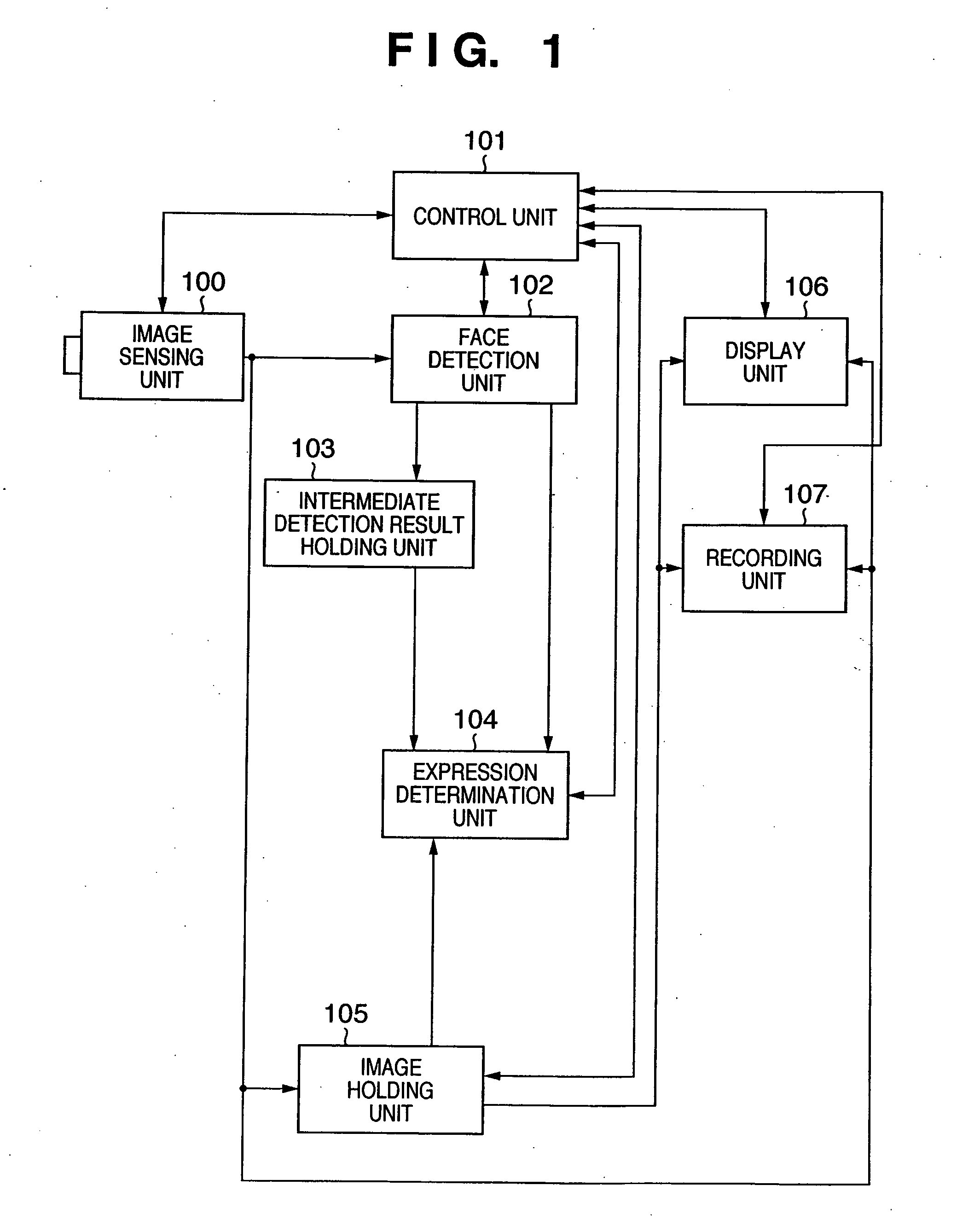
[0154]FIG. 1 is a block diagram showing the functional arrangement of an image processing apparatus according to this embodiment. An image processing apparatus according to this embodiment detects a face from an image and determines its expression, and comprises an image sensing unit 100, control unit 101, face detection unit 102, intermediate detection result holding unit 103, expression determination unit 104, image holding unit 105, display unit 106, and recording unit 107. Respective units will be explained below.

[0155] The image sensing unit 100 senses an image, and outputs the sensed image (photographed image) to the face detection unit 102, image holding unit 105, display unit 106, or recording unit 107 on the basis of a control signal from the control unit 101.

[0156] The control unit 101 performs processes for controlling the overall image processing apparatus according to this embodiment. The control unit 101 is connected to the image sensing unit 100, face detection unit...

second embodiment

[0237] In this embodiment, the detection process of a face detection region (step S202) and the expression determination process (step S204) in the first embodiment are parallelly executed. In this manner, the overall process can be done at higher speed.

[0238]FIG. 3 is a block diagram showing the functional arrangement of an image processing apparatus according to this embodiment. In the arrangement according to this embodiment, the arrangement of an intermediate detection result holding unit 303 and that of an image holding unit 305 are substantially different from those according to the first embodiment.

[0239] The intermediate detection result holding unit 303 further comprises intermediate detection result holding sections A 313 and B 314. Likewise, the image holding unit 305 comprises image holding sections A 315 and B 316.

[0240] The operation of the arrangement shown in FIG. 3 will be described below using the timing chart of FIG. 4.

[0241] In the timing chart of FIG. 4, “A”...

third embodiment

[0252] An image processing apparatus according to this embodiment has as its object to improve the performance of the whole system by parallelly executing the face region detection process executed by the face detection unit 102 and the expression determination process executed by the expression determination unit 104 in the first and second embodiments.

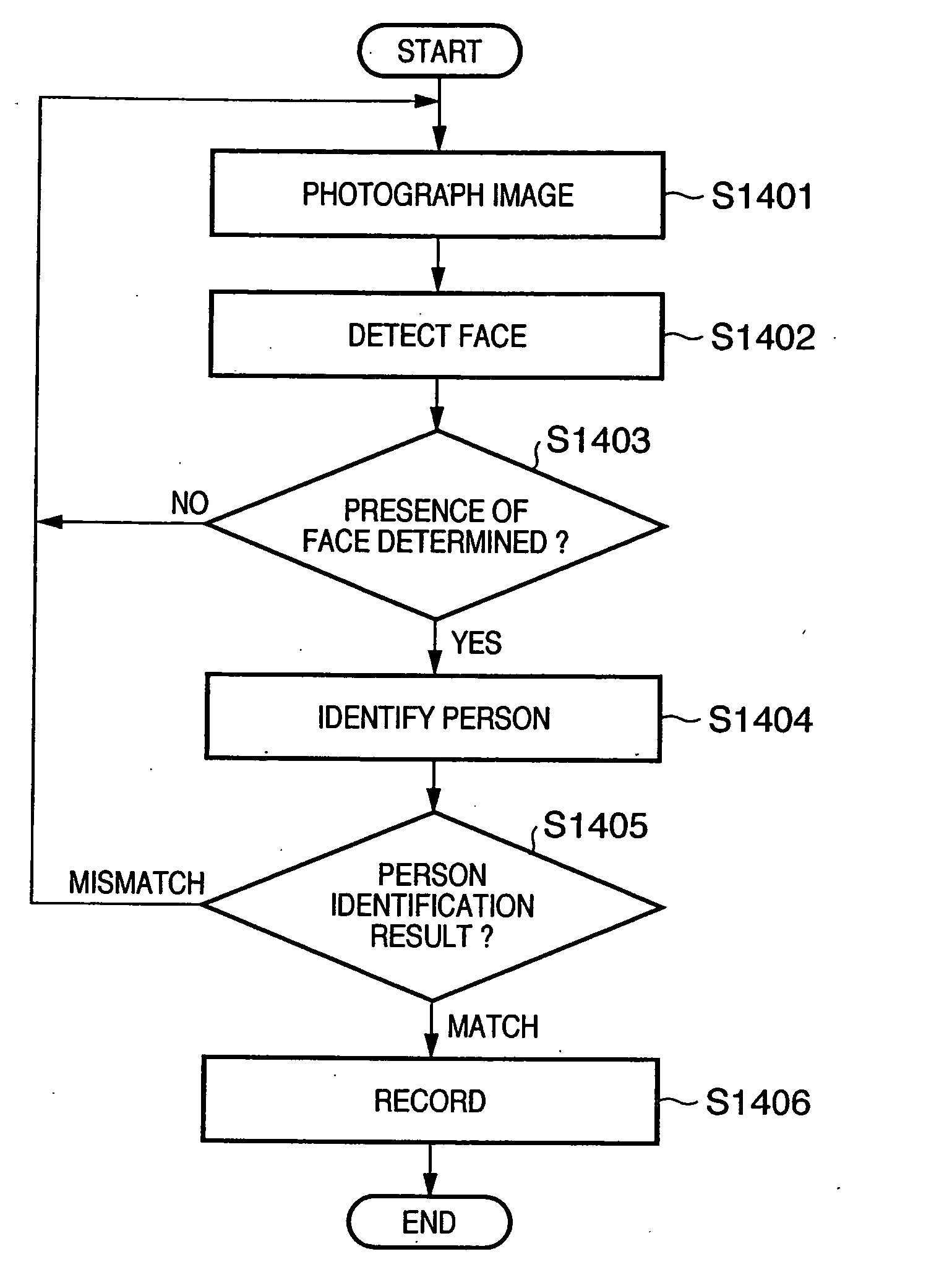
[0253] In the second embodiment, by utilizing the fact that the image photographing and face region detection processes require a longer operation time than the expression determination process, the expression determination process, and the photographing process and face region detection process of the next image are parallelly executed. By contrast, in this embodiment, by utilizing the face that the process for detecting a quartic feature amount shown in FIG. 7D in the first embodiment requires a longer processing time than detection of tertiary feature amounts from primary feature amounts, face region information utilizes the dete...


PUM


Abstract

An image including a face is input (S201), a plurality of local features are detected from the input image, a region of a face in the image is specified using the plurality of detected local features (S202), and an expression of the face is determined on the basis of differences between the detection results of the local features in the region of the face and detection results which are calculated in advance as references for respective local features in the region of the face (S204).

Description

TECHNICAL FIELD [0001] The present invention relates to a technique for making discrimination associated with the category of an object such as a face or the like in an input image. BACKGROUND ART [0002] Conventionally, in the fields of image recognition and speech recognition, a recognition processing algorithm specialized to a specific object to be recognized is implemented by computer software or hardware using a dedicated parallel image processing processor, thus detecting an object to be recognized. [0003] Especially, some references about techniques for detecting a face as a specific object to be recognized from an image including the face have been conventionally disclosed (for example, see patent references 1 to 5). [0004] According to one of these techniques, an input image is searched for a face region using a template called a standard face, and partial templates are then applied to feature point candidates such as eyes, nostrils, mouth, and the like to authenticate a per...

Claims


Application Information

Patent Timeline
Patent Type & Authority Applications(United States)
IPC IPC(8): G06K9/46G06K9/00
CPCG06K9/00221G06K9/00281G06K9/00315G06T2207/10016G06T2207/20084G06T2207/30201G06T7/73G06V40/171G06V40/176G06V40/174G06V20/10G06V40/16
Inventor MORI, KATSUHIKOKANEDA, YUJIMATSUGU, MASAKAZUMITARAI, YUSUKESUZUKI, TAKASHI
Owner CANON KK
Why Eureka
Try Eureka