Device for securing spinal rods

a technology of spinal cord and rod body, which is applied in the field of connecting spinal cord devices, to achieve the effects of convenient and accurate determination, rapid assembly, and streamline surgical procedures

Inactive Publication Date: 2007-03-08
BAILLY FR EMILE
View PDF85 Cites 217 Cited by
  • Summary
  • Abstract
  • Description
  • Claims
  • Application Information

AI Technical Summary

Benefits of technology

[0012] One advantage of the present invention is that it provides a method of spinal stabilization which permits a surgeon to easily and accurately ascertain that the spinal rod, being attached to the patient's spine or vertebrae, is properly aligned before finally fixing the pedicle screws into the vertebral bodies. This is accomplished by using a locking cap configured to engage the body and the spinal rod. Upon rotation of the locking cap relative to the body, the position of the body and the locking cap are secured relative to the spinal rod. The system includes a fastener portion extending from the body and configured to engage the spine. The locking cap will not engage the spinal rod and body portion when the spinal rod is not properly aligned with the pedicle screw assembly.
[0013] The few components of the present invention and the ease with which these components can be quickly assembled allow the surgeon to quickly assure that the spinal rods are in alignment while allowing the surgeon to freely adjust the angle of the pedicle screws with respect to the vertical axis of the body (See e.g. FIG. 4E). This is particularly important in the bloody environment which obscures the surgeon's manual access to and visual assessment of the spinal assemblies. Further, the present invention is an improvement over the previous spinal fixation systems because the present invention streamlines the surgical procedure and increases the ease of insertion and alignment, while maintaining the favorable attributes of the other systems. For example, the present invention has fewer parts and requires less time to implant than most of the previous screw and spinal rod systems. The present invention allows for adaptation to each patient's individual characteristics such as the degree of sagittal and / or coronal plane curvature, it also allows for safe and relatively risk-free insertion and manipulation of the spinal assemblies. At the same time, it allows the spinal rod to be aligned during the surgical operation and stay aligned after implantation and while in vivo (inside the patient). Whether the locking cap 1 is in position over body 5 and aligned with the spinal rod 3, or is locked into position (as shown in FIGS. 3, 11 and 12) can be easily ascertained by the surgeon either by feel or by sight.

Problems solved by technology

The locking cap will not engage the spinal rod and body portion when the spinal rod is not properly aligned with the pedicle screw assembly.

Method used


Image

  • Device for securing spinal rods
  • Device for securing spinal rods
  • Device for securing spinal rods

Examples


Embodiment Construction

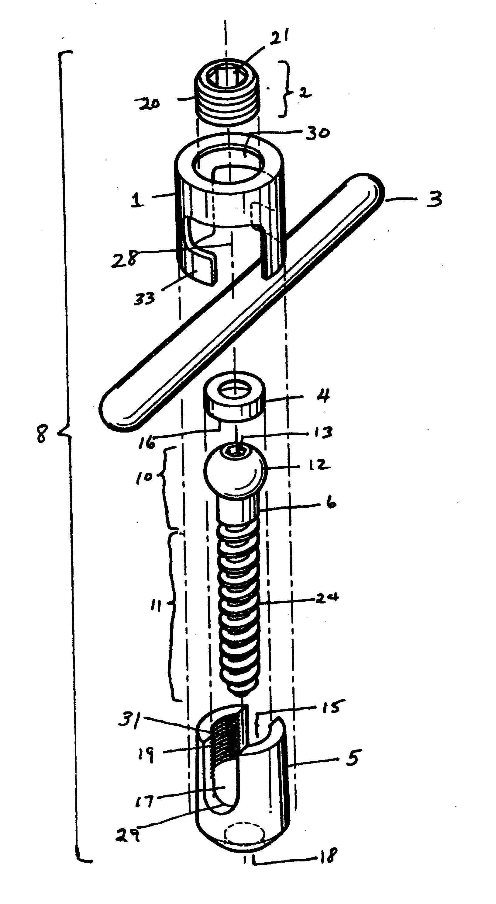
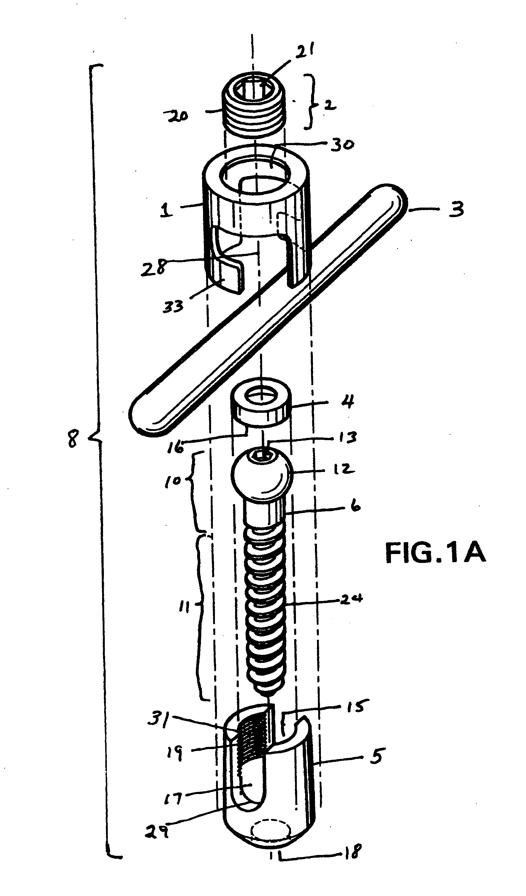
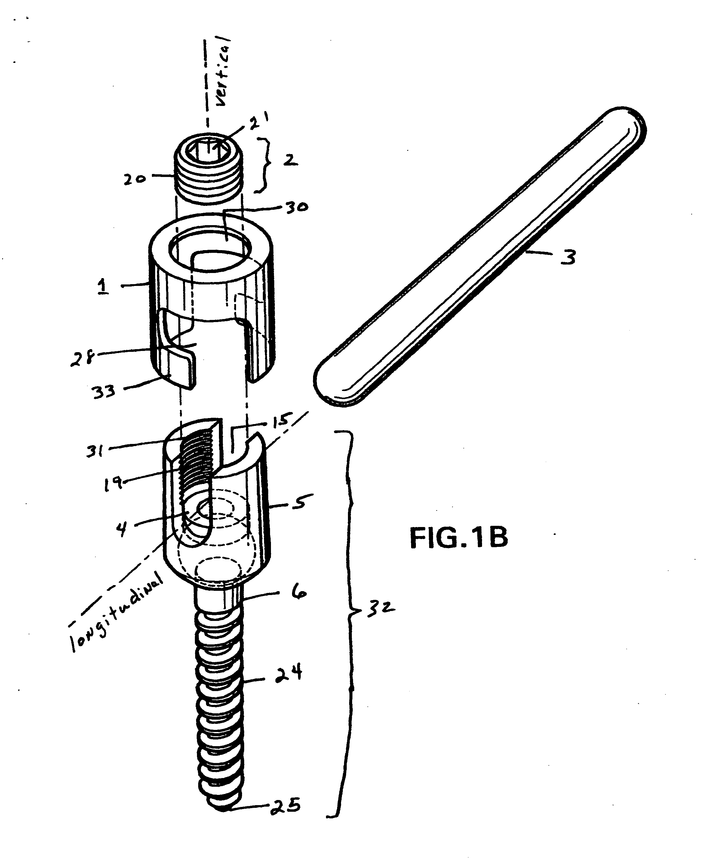
[0031] The present invention's method and device allow a surgeon to determine the alignment and to ensure the alignment of the spinal rod with respect to the pedicle screw assemblies 8, as shown in FIGS. 3 and 12, before finally fixing the pedicle screws into the vertebral bodies. The alignment of the spinal rod is assisted by the locking cap 1. If the spinal rod is not aligned, the locking cap will not lock, this will alert the surgeon to readjust the position or location of one or more pedicle screw assemblies, or to remove the spinal rod and bend it, and to re-insert it and re-test for alignment using the locking cap 1. The locking cap 1 also ensures that the spinal rod remains aligned in vivo after surgery (see FIGS. 11 and 12). Further details are discussed below.

[0032] As shown in the FIGS. 11 and 12, one embodiment of the present invention is a spinal fixation system 7 comprising two or more pedicle screw assemblies 8, which immobilizes and stabilizes vertebral bodies. The p...


PUM


Abstract

The present invention is directed to a device for securing a spinal rod to a fixation device such as a pedicle screw or a lamina hook. The device disclosed herein includes a head portion configured to receive a spinal rod, a locking cap configured to engage the head portion and the spinal rod upon rotation of the locking cap relative to the head portion to secure the position of the head portion and the locking cap relative to the spinal rod, and a fastener portion extending from the head portion and configured to engage the spine. The fastener portion of the device can be in the form of a screw, hook or clamp, or any other configuration known in the art.

Description

RELATED APPLICATION [0001] This application claims the benefit of priority to Provisional Application Number 60 / 703,321, filed on Jul. 27, 2005. [0002] All publications and patent applications cited herein are hereby incorporated by reference to the same extent as if each of them had been individually indicated to be incorporated by reference.TECHNICAL FIELD [0003] The present invention relates to implantable spinal stabilization systems for surgical treatment of spinal disorders, and more particularly, to a device for connecting spinal rods of a spinal stabilization system. BACKGROUND OF THE INVENTION [0004] Various methods of spinal immobilization have been known and used for many years to correct spinal irregularities, instability and displacement, in order to restore stability to traumatized areas of the spine. The preferred treatment for spinal stabilization is immobilization of the joint by surgical fusion, or arthrodesis. Spinal fixation is used, for example, to treat vertebr...

Claims


Application Information

Patent Timeline
Patent Type & Authority Applications(United States)
IPC IPC(8): A61F2/30
CPCA61B17/7037A61B17/7032
Inventor BAILLY, FRANK EMILE
Owner BAILLY FR EMILE
Why Eureka
Try Eureka