Coil spring structure of shutter button camera device and button structure of electronic device

a technology of electronic devices and shutter buttons, which is applied in the direction of wound springs, instruments, mechanical devices, etc., can solve the problems of difficult tasks that require extreme caution, increase the number of functions, and complicated internal circuit technology, etc., and achieves simple and reliable manner, smooth pressing

Inactive Publication Date: 2011-04-19
PANASONIC CORP
View PDF18 Cites 43 Cited by
  • Summary
  • Abstract
  • Description
  • Claims
  • Application Information

AI Technical Summary

Benefits of technology

[0016]A first objective of the present invention is to provide a camera device with a shutter button that can be smoothly pressed. In addition, a second objective of the present invention is to provide a camera device with a shutter button that can be assembled in a simple and reliable manner.
[0020]The present invention makes it possible to achieve smooth pressing of the shutter button, as well as to allow workers, no matter who they are, to always position the coil spring at the center of the shutter button.
[0021]The first winding portion is preferably provided so as to continue from one end of the second winding portion. By inserting the boss portion into the first winding portion during assembly of a switch pressing mechanism, it becomes possible to readily and reliably attach the coil spring to the shutter button.
[0022]In addition, the coil spring may further include a third winding portion wound into a third shape about the central axis, the third shape being included in the second winding portion. By providing the first and third winding portions at opposite ends of the coil spring, it becomes possible to more reliably fit the coil spring on the boss portion as compared to the case where the coil spring includes only the first winding portion. In addition, it is possible to eliminate the necessity of checking the end portion of the coil spring to confirm whether the coil spring has been fitted from the appropriate end during assembly work, resulting in improvement in workability.

Problems solved by technology

While the size and the thickness are being reduced, the number of functions tends to be increased, so that technology for internal circuits, etc., is becoming complicated and advanced.
Therefore, assembling the switch pressing mechanism RSp and integrating it into the digital camera 1a are difficult tasks that require extreme caution.

Method used


Image

  • Coil spring structure of shutter button camera device and button structure of electronic device
  • Coil spring structure of shutter button camera device and button structure of electronic device
  • Coil spring structure of shutter button camera device and button structure of electronic device

Examples


Embodiment Construction

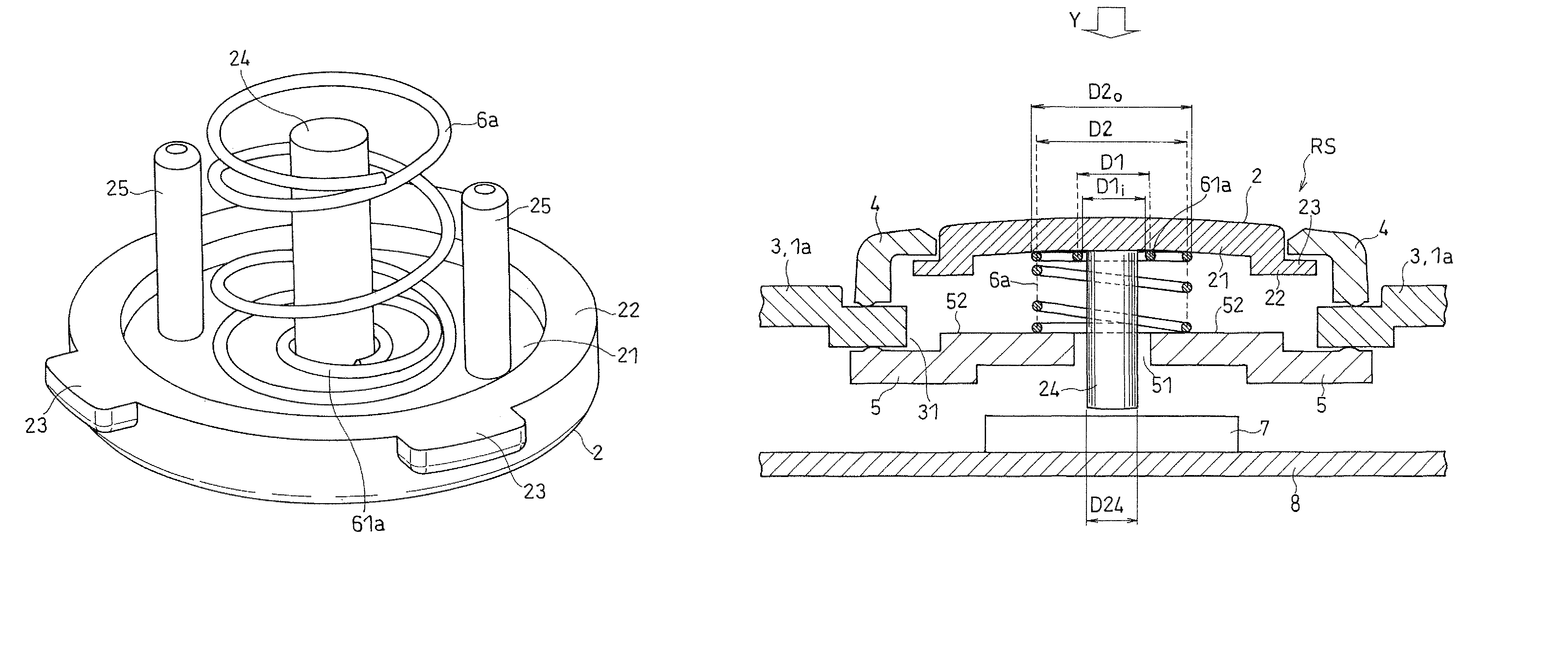
[0035]Before describing an embodiment of the present invention in detail with reference to the drawings, a switch pressing mechanism of a camera device according to the present invention will be described in terms of its technical features. The above-described problems pertinent to conventional switch pressing mechanisms are considered to be due to the coil spring moving in the diameter direction of the boss. Therefore, the present invention additionally provides means for aligning the coil spring with the boss in the diameter direction without compromising the size and thickness reduction of the switch pressing mechanism, thereby making it possible to achieve smooth pressing of the switch.

[0036]Concretely, unlike the conventional coil spring 6p, a coil spring 6 according to the present invention is basically defined with at least two diameters D1 and D2 that satisfy the following equations (1) and (2).

D1

D1≈D24   (2)

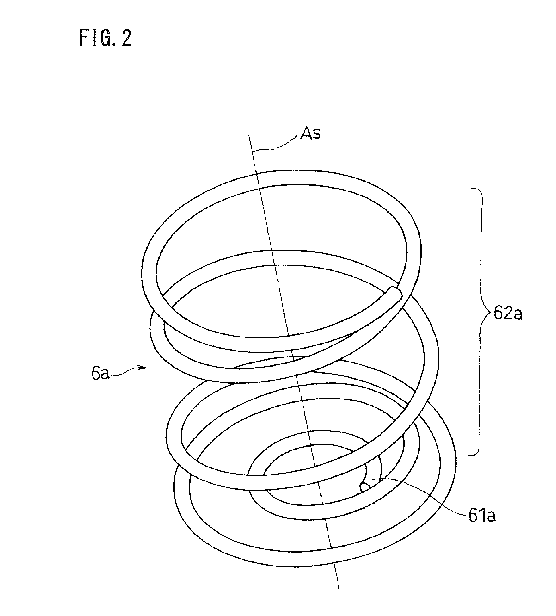
[0037]For convenience of explanation, a portion of the coi...


PUM


Abstract

In a camera device 1a with a shutter button 2 for transmitting an externally-applied pressing force to a switch 7, a boss 24 has a first end attached to the shutter button 2, and a second end opposed to the switch 7, a coil spring 6a has a first winding portion 61a and a second winding portion 62a, which are respectively wound into first and second shapes about a common central axis As, the second shape includes the first winding portion 61a, and the second end of the boss 24 is inserted into the first winding portion 61a.

Description

FIELD OF THE INVENTION[0001]The present invention relates to camera devices with a spring-biased shutter button.BACKGROUND OF THE INVENTION[0002]Recent years have seen the increasing popularity of digital cameras among other camera devices, and the number of digital cameras produced is increasing yearly. In general, the digital cameras are roughly classified into single-lens reflex type and compact type. Recently, the digital cameras of the single-lens reflex type are increasingly being shipped, but as for the digital cameras of the compact type, small and slim digital cameras are also still popular. To achieve such size and thickness reduction of the cameras, Japanese Laid-Open Patent Publication No. 2002-350943 proposes technology for improving, for example, the structure of a battery chamber with battery connectors directly attached to a switch.[0003]While the size and the thickness are being reduced, the number of functions tends to be increased, so that technology for internal ...

Claims


Application Information

Patent Timeline
Patent Type & Authority Patents(United States)
IPC IPC(8): G03B17/00
CPCG03B17/00
Inventor SAIKI, JUN
Owner PANASONIC CORP
Why Eureka
Try Eureka