Pressure-assistant thin-wall blank precise processing method

A technology of precision machining and blanks, which is applied in the field of precision machining of thin-walled blanks, can solve the problems that the shape and dimensional accuracy of the final parts cannot be guaranteed, and achieve the effects of low cost, large movement space, and reasonable design

Active Publication Date: 2015-09-09
HARBIN INST OF TECH
View PDF6 Cites 10 Cited by
  • Summary
  • Abstract
  • Description
  • Claims
  • Application Information

AI Technical Summary

Problems solved by technology

[0005] The present invention aims to solve the problem that the existing cutting processing methods and devices cannot avoid complex deformation or movement during cutting of large-size thin-wa

Method used


Image

  • Pressure-assistant thin-wall blank precise processing method
  • Pressure-assistant thin-wall blank precise processing method
  • Pressure-assistant thin-wall blank precise processing method

Examples


specific Embodiment approach 1

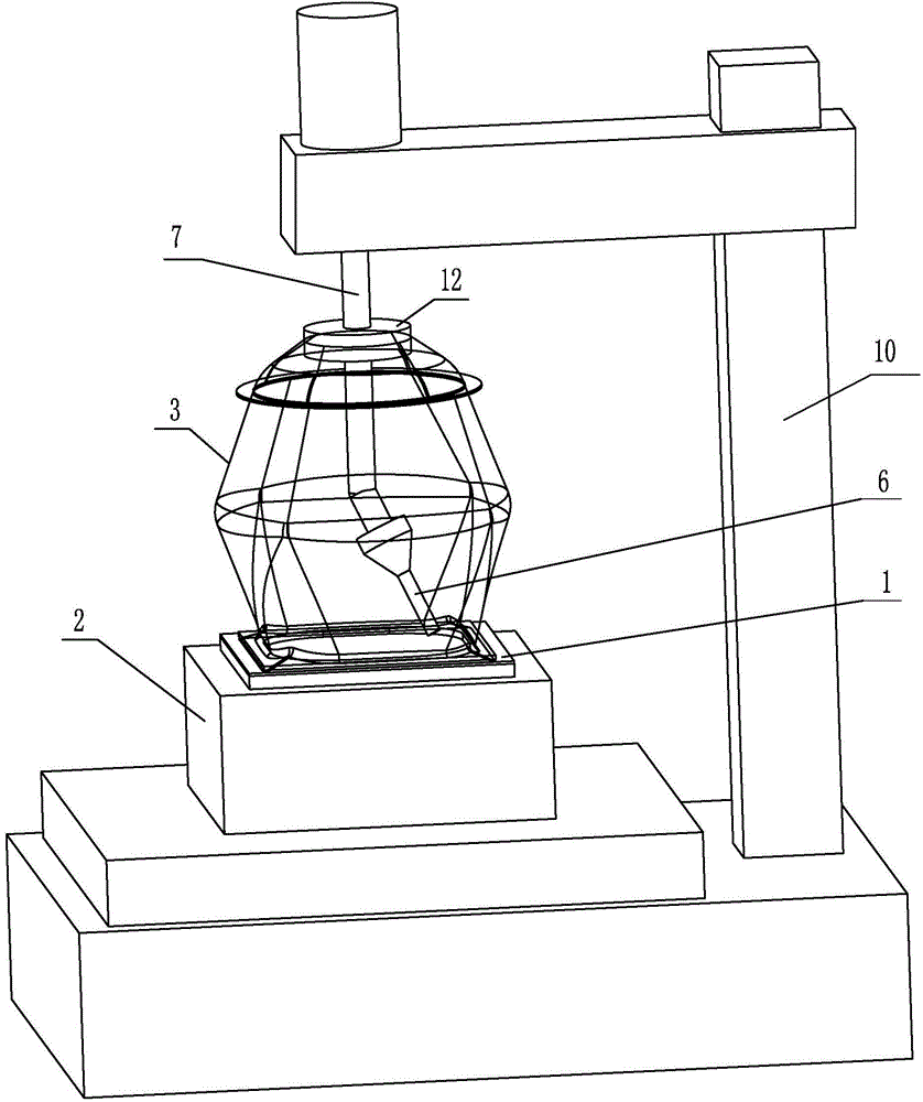
[0020] Specific implementation mode one: combine Figure 1-6 To illustrate, a pressure-assisted precision machining method for thin-walled blanks in this embodiment is implemented in accordance with the following steps:

[0021] Step 1, placing the blank 1 to be processed on the support tire mold 2;

[0022] Step 2, placing the pressure medium chamber 3 on the blank 1 to be processed, so that the lower end of the pressure medium chamber 3 is in close contact with the peripheral area of ​​the blank 1 to be cut to realize sealing;

[0023] Step 3: Fill medium 5 into the pressure medium cavity 3, the pressure of the medium is 0.2-10MPa, and use the medium 5 to press the blank 1 to be cut tightly against the support tire mold 2;

[0024] Step 4, using the cutting tool 6 placed inside the pressure medium cavity 3 to cut the blank 1 to be cut to obtain the final required parts;

[0025] Step 5, remove the pressure in the pressure medium chamber 3, remove the cutting tool 6 and the...

specific Embodiment approach 2

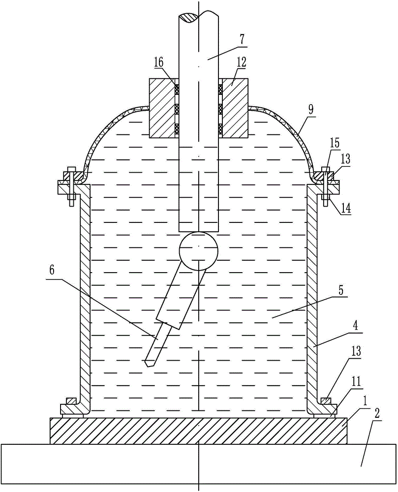
[0028] Specific implementation mode two: combination figure 1 , figure 2 , Figure 5 and Figure 7 Note that the pressure medium cavity 3 used in step 2 of this embodiment is a composite structure of a rigid pressure medium cylinder 4 and a flexible bladder 9, and a sealing strip 11 is provided between the lower end of the rigid pressure medium cylinder 4 and the blank 1 to be cut. The rigid pressure medium cylinder 4 is pressed against the blank 1 to be cut by the briquetting block 13 to realize the sealing between the rigid pressure medium cylinder 4 and the blank 1 to be cut; Compounding, the specific way of compounding is to use bolts 15 and nuts 14 to squeeze each other between the briquetting block 13 and the rigid pressure medium cylinder 4, so as to realize the sealing between the extruded flexible bag 9 and the rigid pressure medium cylinder 4; the upper end of the rigid pressure medium cylinder 4 A sealing ring 12 is provided, and the flexible bag 9 is hermetical...

specific Embodiment approach 3

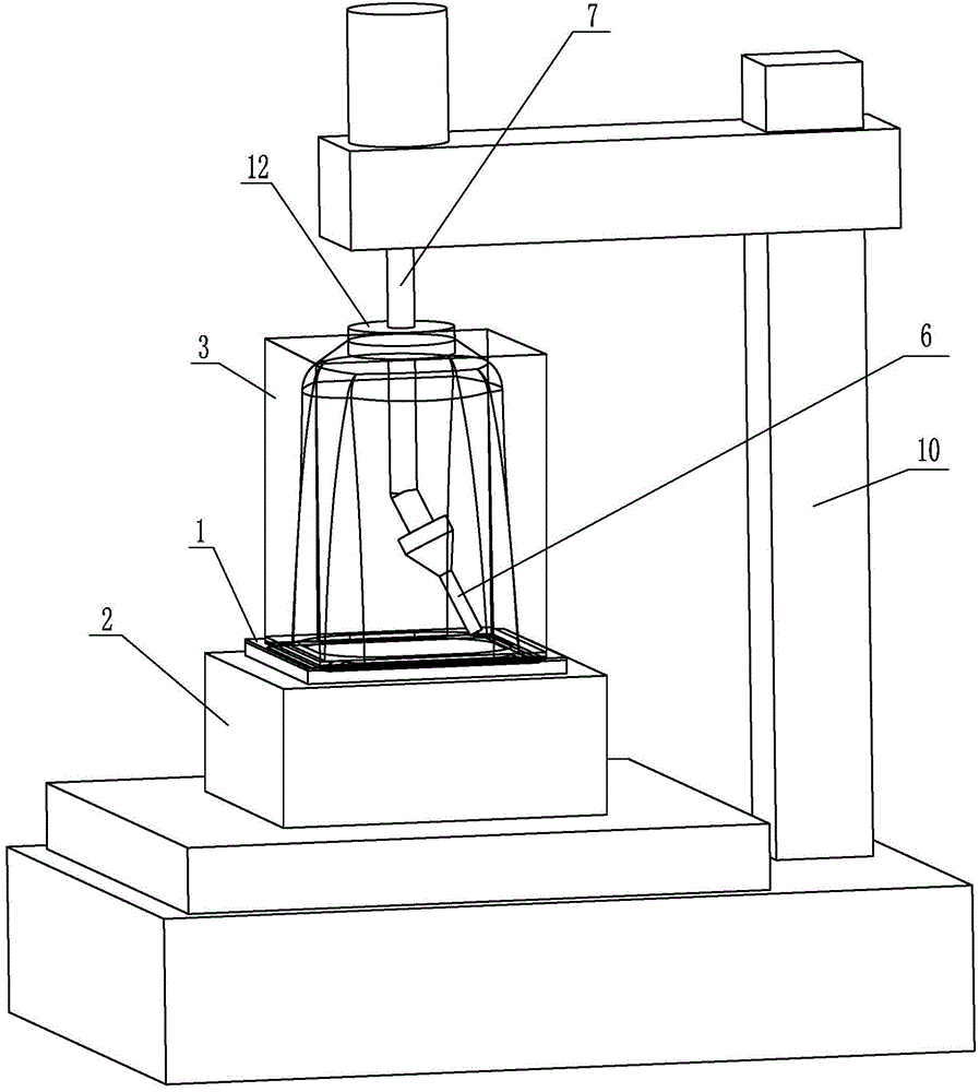
[0032] Specific implementation mode three: combination image 3 , Figure 4 , Image 6 and Figure 7 Explain that the pressure medium cavity 3 adopted in the second step of this embodiment is a composite structure of the rigid constraining frame 8 and the flexible bladder 9, and the lower end of the rigid constraining frame 8 uses a pressing block 13 to press the lower edge of the flexible bladder 9 against the surface to be cut. On the processed blank 1, the upper part of the flexible bag 9 is sealed between the sealing ring 12 and the actuator 7, so that a pressure medium cavity is formed between the flexible bag 9 and the blank 1 to be cut.

[0033] The pressure medium cavity 3 used in step 2 is a composite structure of the rigid constraint frame 8 and the flexible capsule 9, and the lower end of the rigid constraint frame 8 presses the lower edge of the flexible capsule 9 against the blank 1 to be cut, so that the flexible capsule 9 A pressure medium cavity is formed be...


PUM

PropertyMeasurementUnit
Tensile strengthaaaaaaaaaa

Abstract

The invention discloses a pressure-assistant thin-wall blank precise processing method, relating to a precise processing method of a thin-wall blank and solving the problem that the shape and size precision of the final part cannot be guaranteed as an existing cutting processing method and device cannot avoid complex deformation or movement of large-size thin-wall blank during the cutting process. The method comprises the main steps of: step 1, placing a to-be-cut blank on a support molding bed and positioning the blank; step 2, placing a pressure medium cavity on the to-be-processed blank; step 3, filling a medium with the pressure medium cavity; step 4, cutting the to-be-cut blank by utilizing a cutting tool placed inside the pressure medium cavity to obtain a finally needed part; step 5, removing pressure in the pressure medium cavity, moving away the cutting tool and the pressure medium cavity and taking the part out. The pressure-assistant thin-wall blank precise processing method is used for precise processing of the thin-wall blank.

Description

technical field [0001] The invention relates to a precision machining method for thin-walled blanks, in particular to a pressure-assisted precision machining method for thin-walled blanks. Background technique [0002] In the field of aerospace, there are many large-sized sheet metal parts, the size of which can reach 2m or more in one direction in the plane, and the thickness is generally in the range of 5-30mm, which is a typical thin-walled sheet metal part. Such parts usually use the original slab with equal wall thickness, and make the required single curvature parts or parts with complex curved surface shapes through plastic forming processes such as drawing, deep drawing or roll bending. In order to further reduce the weight of the parts, it is necessary to perform cutting or chemical milling on the parts after plastic forming to remove excess material at local positions, and to maximize the final parts while ensuring the overall mechanical properties and stiffness re...

Claims


Application Information

Patent Timeline
IPC IPC(8): B23Q3/00
CPCB23Q3/00B23Q2703/04
Inventor 何祝斌苑世剑
Owner HARBIN INST OF TECH
Why Eureka
Try Eureka