Noise and shock reduction in rotary positive displacement blowers

Inactive Publication Date: 2012-08-02
TUTHILL CORP
View PDF6 Cites 4 Cited by
  • Summary
  • Abstract
  • Description
  • Claims
  • Application Information

AI Technical Summary

Benefits of technology

[0002]The invention relates to rotary positive displacement blowers (of the Roots type) and, more particularly, to a back-pass loop for gradually pressurizing the working cell to outlet pressure in order to weaken the strength of the pulsations that would otherwise happen without such a back-pass loop, and thereby reduce noise and shock (and perhaps better efficiency as well).
[0012]In common with one of the objects of the invention here, an object of the invention for the Acoustic Air design included reducing pressure pulsations, and thereby reducing resulting noise and vibration.

Problems solved by technology

In other words, the backflow loop was not as effective as hoped for.
Noise and vibration are serious problems.

Method used


Image

  • Noise and shock reduction in rotary positive displacement blowers
  • Noise and shock reduction in rotary positive displacement blowers
  • Noise and shock reduction in rotary positive displacement blowers

Examples


Embodiment Construction

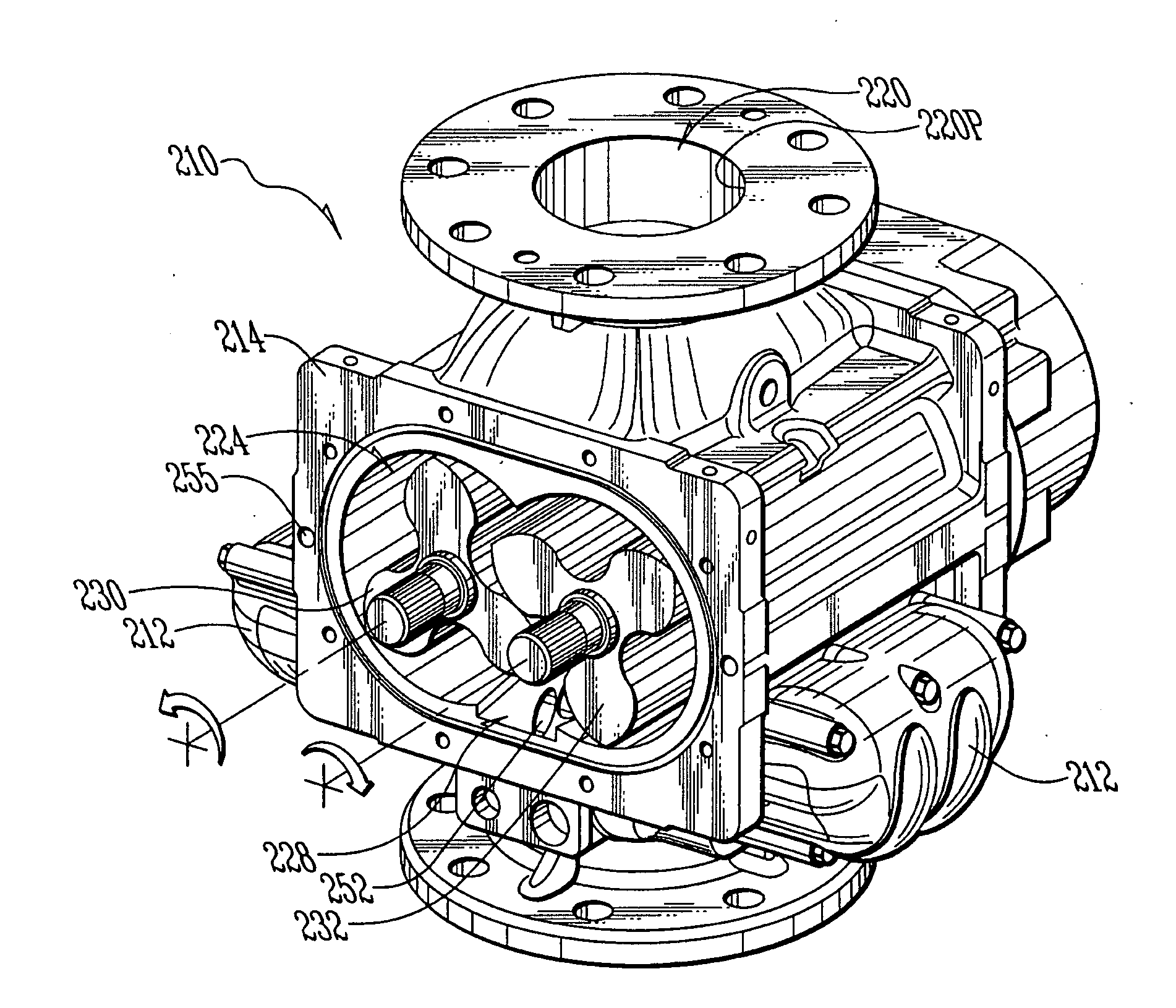
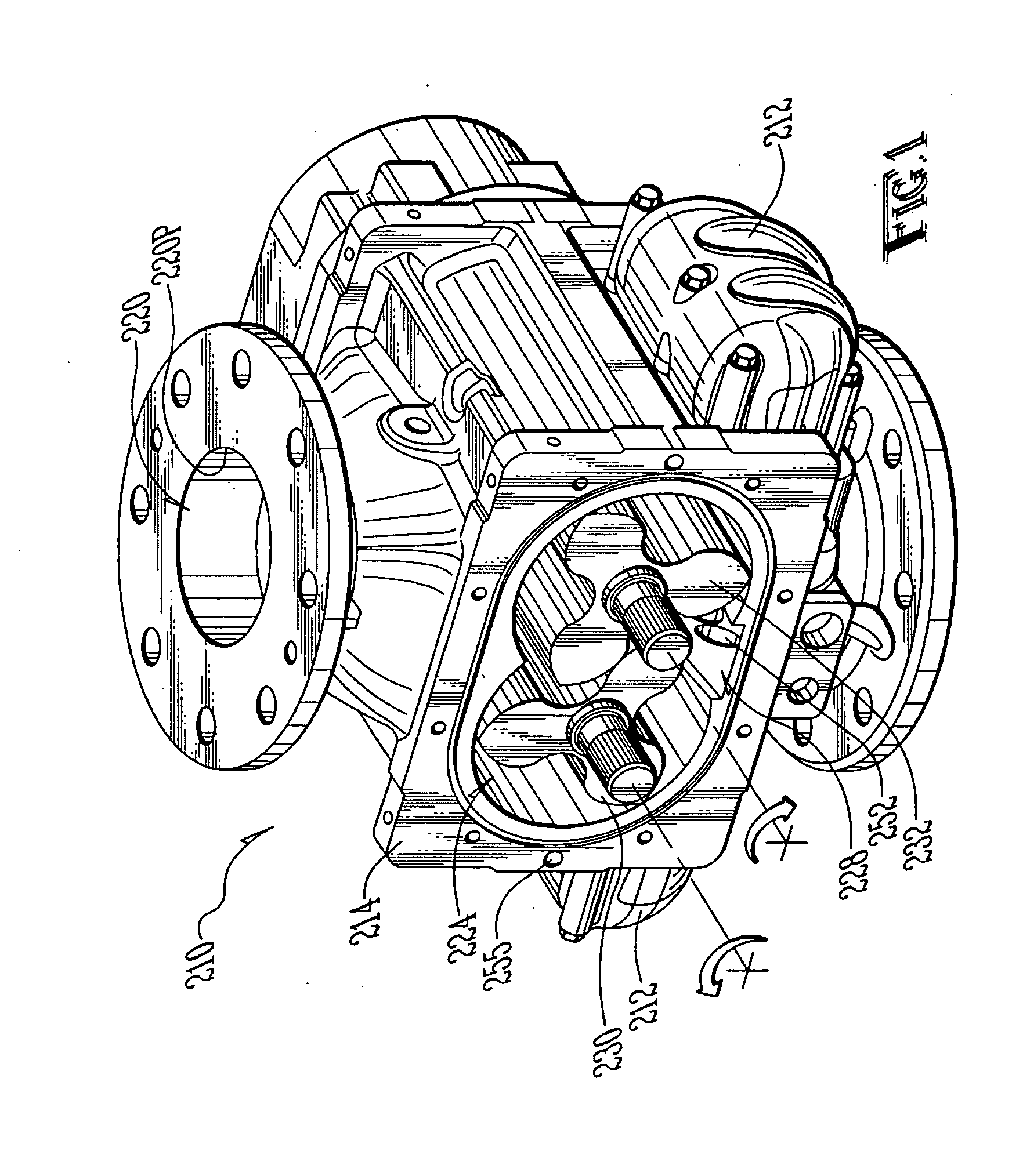
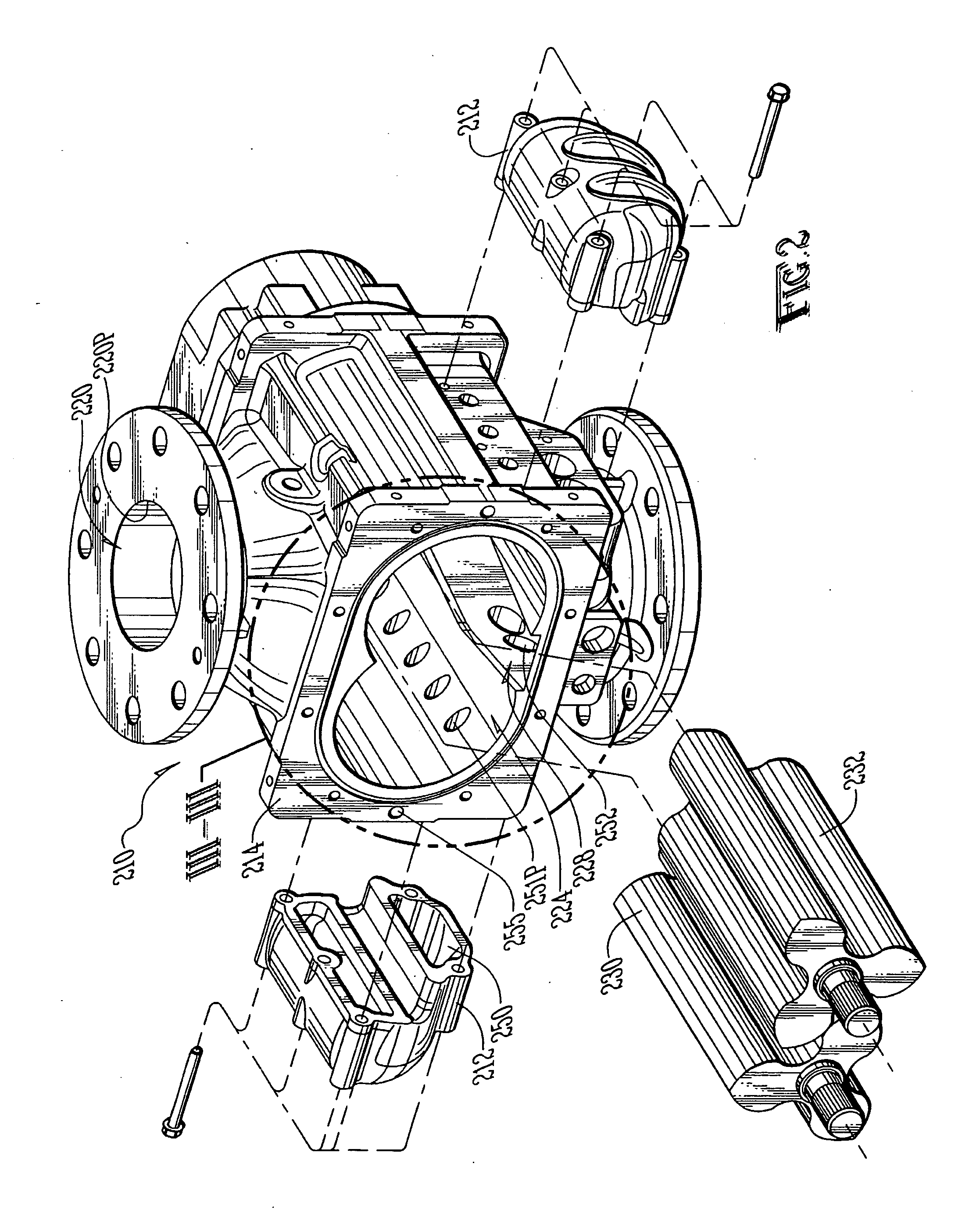
[0024]FIGS. 1 through 4 provide line drawings of a rotary positive displacement blower 210 with noise and shock reduction improvements in accordance with the invention. It is an aspect of the invention to incorporate a pair of back-pass manifolds 212.

[0025]This is a Roots style blower. FIG. 4 shows better that, it has a substantially hollow housing 214 defining an inlet plenum 220, a rotor chamber 224, and a discharge plenum 228. (Preferably the housing 214 is cast, but the flange surfaces would be machined and ground.)

[0026]A pair of rotors 230 are disposed in the rotor chamber 224. The rotors 230 would be sealed inside by a pair of opposed end plates (far side end plates shown in FIGS. 1 and 2). The rotors 230 are driven to rotate counter-rotationally to each other. For instance, the left rotor 230 rotates counter-clockwise (CCW).

[0027]In the drawings, the blower 210 is shown with the inlet port 220P up and the discharge port 228P down. However, the blower 210 can be mounted in an...


PUM


Abstract

A roots-style blower (210) has a housing (214), rotors (230) and manifolds (212) for the housing (214). The housing (214) forms an inlet plenum (220), a rotor chamber (224) and a discharge plenum (228). The rotors (230) have straight lobes (232) spaced by pockets (240). The pocket (240X) that traps gas between a leading and following lobe (232) and an inside wall of the rotor chamber (224) is a temporary closed cell (240X). The manifolds (212) and the housing (214) form a pair of back-pass loops (250-251), one for each rotor (230). Each back-pass loop (250-252) comprises a back-pass chamber (250), outer channels (252) from the discharge plenum (228) to the back-pass chamber (250), and inner channels (251) to the rotor chamber (224). Wherein, the back-pass chamber (250) volume as a percentage of closed cell (240X) volume ranges between about fifty-six percent (56%) and one-hundred-seventeen percent (117%).

Description

CROSS-REFERENCE TO PROVISIONAL APPLICATION(S)[0001]This application claims the benefit of U.S. Provisional Application No. 61 / 336,495, filed Jan. 22, 2010, the disclosure of which is incorporated herein by this reference thereto.BACKGROUND AND SUMMARY OF THE INVENTION[0002]The invention relates to rotary positive displacement blowers (of the Roots type) and, more particularly, to a back-pass loop for gradually pressurizing the working cell to outlet pressure in order to weaken the strength of the pulsations that would otherwise happen without such a back-pass loop, and thereby reduce noise and shock (and perhaps better efficiency as well).[0003]Briefly, the performance of such blowers is typically measured (or specified) in terms of the following factors:—flow, pressure, efficiency, noise, and reliability.[0004]It is an object of the invention to provide improvements in particular for at least two or three of those factors, namely, noise and reliability, plus perhaps efficiency.[000...

Claims


Application Information

Patent Timeline
IPC IPC(8): F01C1/18
CPCF04C18/126F04C2240/30F04C29/068F04C29/065
Inventor FITZPATRICK, ERICH R.BUIS, MICHAEL R.JONES, JR., CHARLES R.
Owner TUTHILL CORP
Why Eureka
Try Eureka