Flow controlled switching valve

a technology of switching valve and flow control, which is applied in the direction of valve housing, valve operating means/release devices, cleaning using liquids, etc., can solve the problems of reducing the net pulling force produced by the traction nozzle, affecting the effective deployment of the high pressure hose,

Active Publication Date: 2012-08-16
STONEAGE
View PDF2 Cites 15 Cited by
  • Summary
  • Abstract
  • Description
  • Claims
  • Application Information

AI Technical Summary

Benefits of technology

[0011]When flow is again restored by the operator turning flow back on, the poppet moves forward, rotating via the guide, to the first position. In the first position, the radial arms are aligned with the passages through the mid portion of the valve body, thus closing the passages. At the same time, the poppet is prevented from closing the outlet portion, thus permitting fluid flow past the poppet and out the outlet end of the valve to the cleaning nozzle attached to the front end of the switching valve.

Problems solved by technology

This counterforce hinders effective deployment of the high pressure hose and reduces the net pulling force produced by the traction nozzle on the high pressure hose.

Method used


Image

  • Flow controlled switching valve
  • Flow controlled switching valve
  • Flow controlled switching valve

Examples


Embodiment Construction

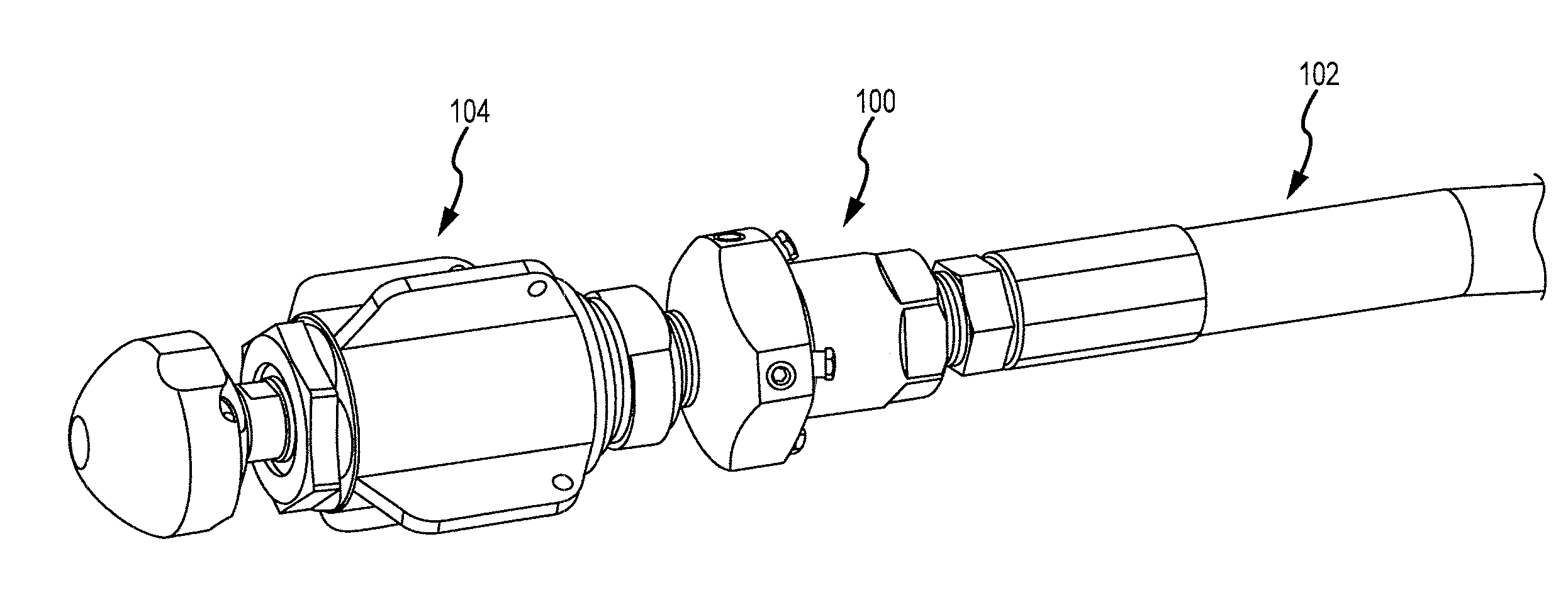
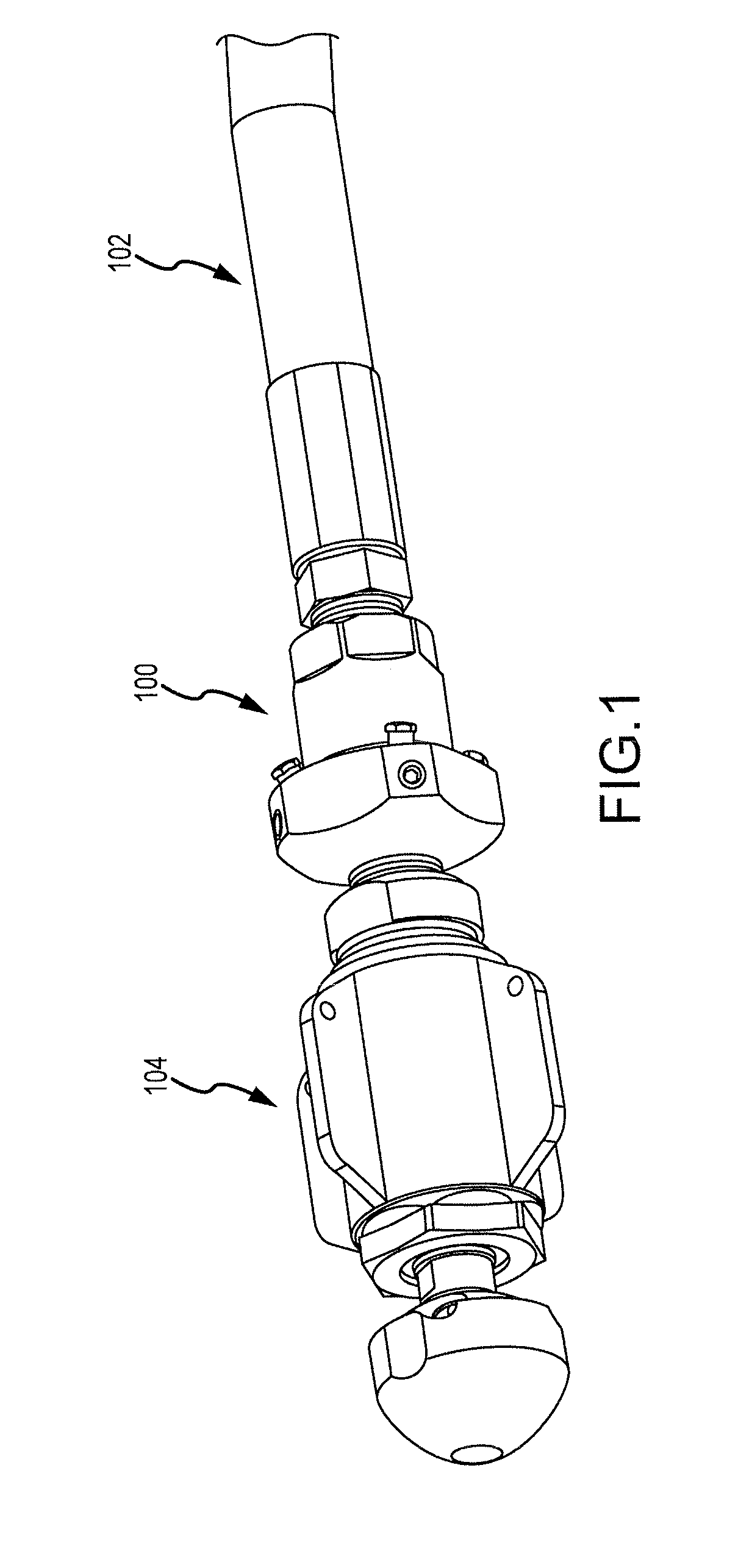
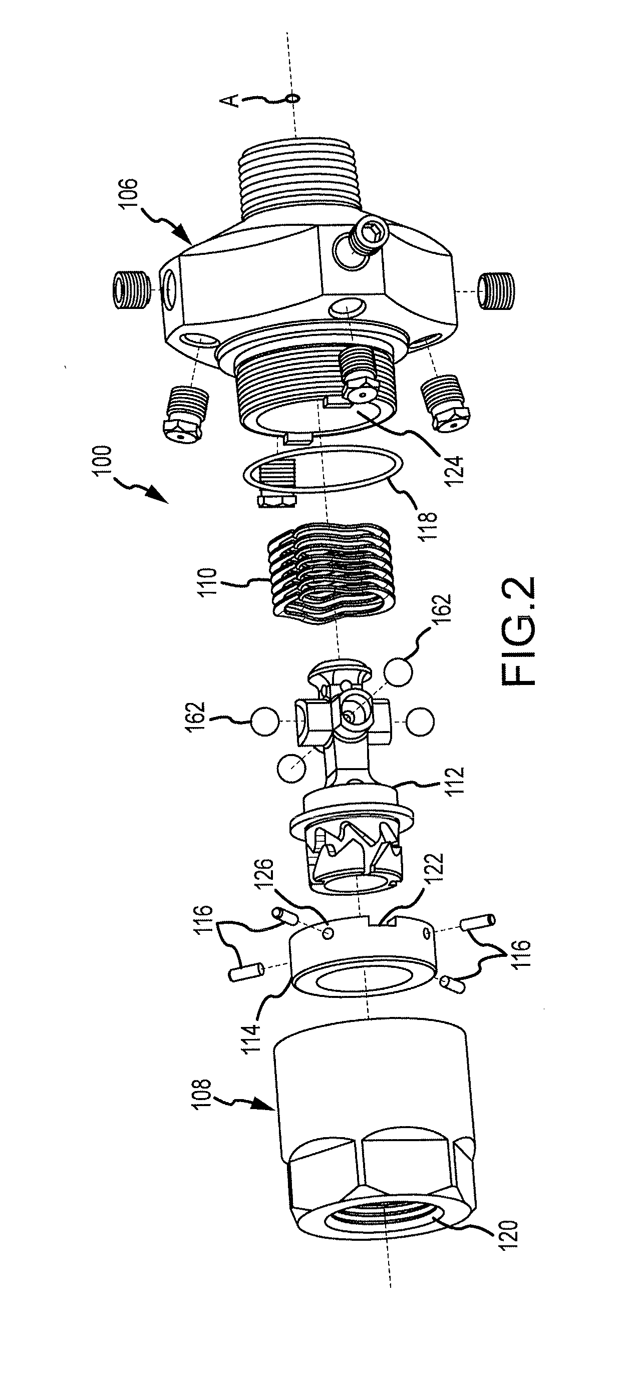
[0020]An exemplary embodiment of a switching valve 100 is shown in FIG. 1 connected to a high pressure fluid hose 102 and to a cleaning nozzle 104. The switching valve 100 essentially has a generally cylindrical compact outer shape so that it can be inserted into pipes and other tubular passages. A separate exploded perspective view of the valve 100 is shown in FIG. 2. As shown in FIG. 2, the valve 100 includes a hollow main valve body 106 and an inlet end guide cap 108. Inserted into the main valve body 106 is a spring 110 and a poppet member 112. Inserted into the inlet end guide cap 108 is a guide collar 114 which carries four equally spaced guide pins 116. The inlet end guide cap 108 is sealed with an 0-ring 118 and threaded onto the valve body 106, thus capturing together the poppet member 112, spring 110, guide collar 114 with guide pins 116.

[0021]The inlet end cap 108, at its rear, may have internal threads 120 as shown or alternatively may have external threads to mate with ...


PUM


Abstract

A flow path switching valve is disclosed that can be operated remotely simply by turning flow on and off. A mid portion of the body has at least one passage therein leading from a central axial bore to one or more external ports each having a tractor nozzle. The valve outlet connects the axial bore to a cleaning nozzle. A poppet member is received in the central axial bore. In a first position, the poppet member directs fluid flow through the outlet to the cleaning nozzle connected to the outlet. The poppet member, when in a second position, closes the central axial bore through the outlet end of the valve body and permits fluid flow through the tractor nozzles. Selection of the different flow paths is made by simply reducing flow through the valve below a predetermined fluid flow threshold and then increasing the flow rate above the threshold.

Description

BACKGROUND OF THE DISCLOSURE[0001]Traction nozzles are used in sewer pipe lines and other piping systems to assist in pulling high pressure hose into the pipe to reach obstructions requiring removal. These traction nozzles have jet tips oriented at an angle rearward in order to generate thrust in the nozzle within the pipe to assist in pulling the hose through and along long stretches of pipe and around pipe bends. These nozzles have forward directed jet tips to ablate the obstructions encountered. However, the forward directed jet tips produce a counter force against forward travel of the nozzle through the pipe. This counterforce hinders effective deployment of the high pressure hose and reduces the net pulling force produced by the traction nozzle on the high pressure hose. Thus there is a need for a switching mechanism that does not generate a counterforce during traction operation, yet facilitates operation of an effective fluid jet nozzle during actual cleaning operations.SUMM...

Claims


Application Information

Patent Timeline
Patent Type & Authority Applications(United States)
IPC IPC(8): B08B9/02
CPCB08B9/0495B05B1/14B05B13/0627B08B3/02F16K31/58F16K11/04F16K31/1635B05B1/1681B05B1/3006B05B3/06B05B12/04B05B13/0636B08B9/0497E03F9/00Y10T137/4245Y10T137/4259Y10T137/86485Y10T137/87788Y10T137/87804Y10T137/87861B05B3/0463
Inventor ZINK, GERALD P.
Owner STONEAGE
Why Eureka
Try Eureka