
Airbag cushion

a technology for airbags and cushioning, applied in the direction of pedestrian/occupant safety arrangements, vehicular safety arrangements, vehicle components, etc., can solve the problems of time and complexity of design, and achieve the effect of limiting outward movement and limiting outward movement of the inflated airbag cushion

Inactive Publication Date: 2012-08-16
KEY SAFETY SYST
View PDF2 Cites 11 Cited by
  • Summary
  • Abstract
  • Description
  • Claims
  • Application Information

AI Technical Summary

Benefits of technology

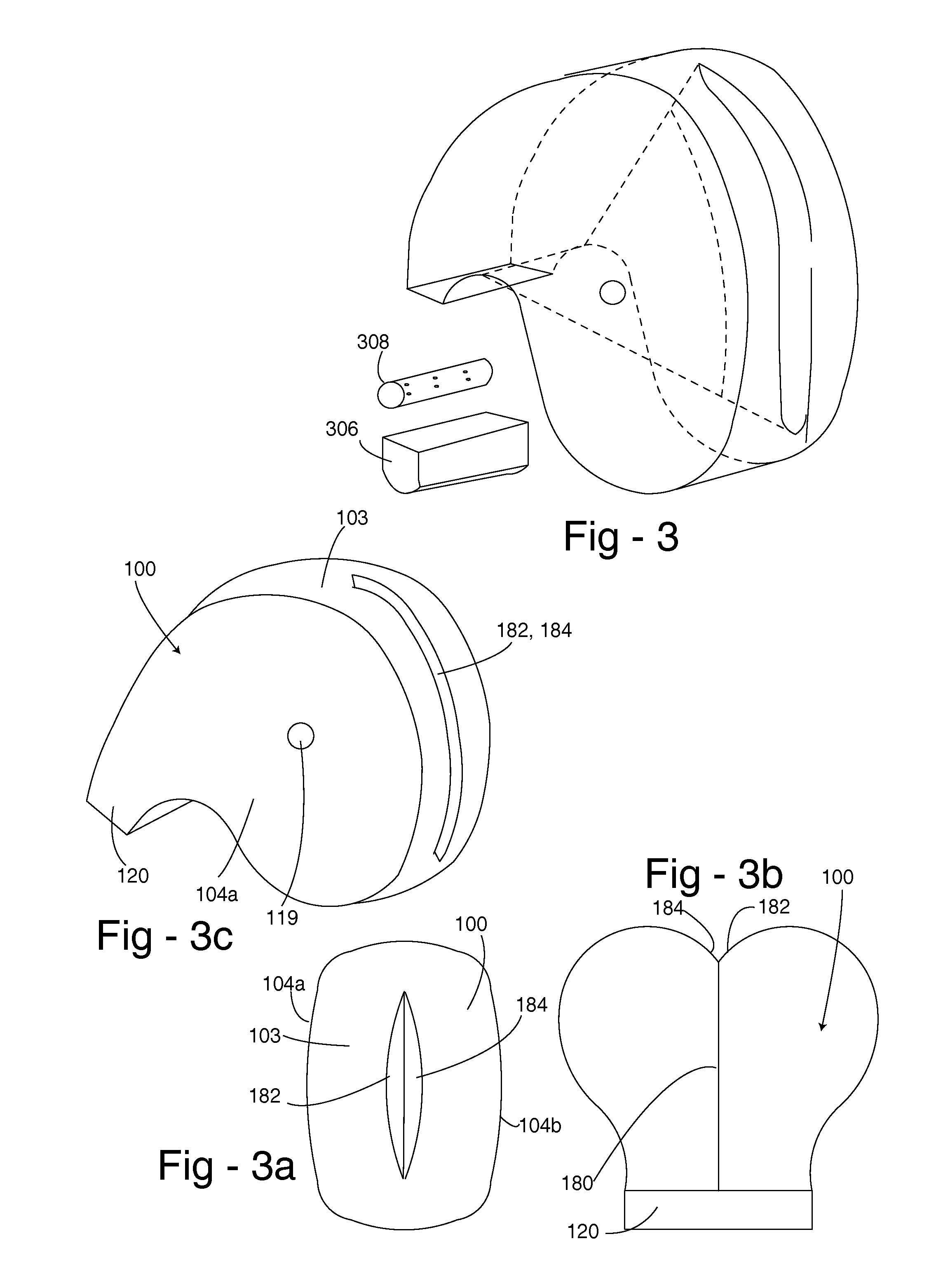
[0011]An airbag cushion with a recessed portion formed on an exterior of the airbag cushion has a pair of side panels and a tether for limiting outward movement of the inflated airbag cushion; and wherein the tether forms a portion of the exterior surface of the airbag cushion. The preferred embodiment airbag cushion further has a central panel interposed between the pair of side panels and attached along edges of each side panel defining a single inflatable chamber with a gas inlet passageway. This central panel has a cut out; and the tether for limiting outward movement of the inflated airbag cushion, has one end of the tether attached to the central panel proximate the cut out and the opposite end of the tether secured to the central panel proximate the gas inlet passage. The pair of side panels, the central panel, and portions of the tether form the exterior surface of the airbag cushion. The side panels have a curved outer periphery. The tether has a main tether panel portion for limiting the outward movement of the cushion The main tether panel portion has an outer groove forming portion, the groove forming portion being part of the exterior surface of the airbag cushion. The tether also has a groove panel sewn or otherwise attached to the main tether panel portion, the groove panel being similarly sized and shaped to the outer groove portion of the main tether panel portion and being part of the exterior surface of the airbag cushion, the tether having a “y” shape when viewed in a cross section.

Problems solved by technology

As can be appreciated, the use of many small pieces of material used to form the grooved or recessed portions of the airbag cushion added to the time and complexity of the design.

Method used


Image

  • Airbag cushion
  • Airbag cushion
  • Airbag cushion

Examples


Embodiment Construction

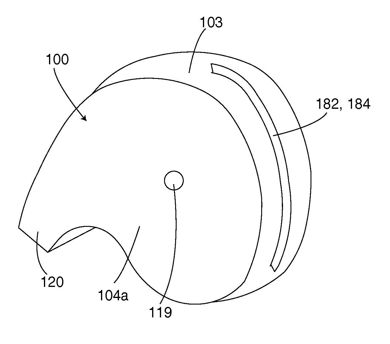
[0034]Airbag cushion 100 shown in FIGS. 3, 3a, 3b, 3c, 4, 4a, 4b and 5 includes a center panel 102 having a face panel portion 103, which faces the occupant to be protected, and a plurality of side panels 104a and 104b. Each of the above panels is made typically from woven airbag material comprising nylon or polyester. Each of the side panels 104a and 104b is substantially identical and the mirror image of the other. Each of the side panels 104a and 104b includes a neck portion 120 and a main portion 122. Each side panel 104a, 104b may optionally include a vent hole 119. The center panel 102 also includes a plurality of opposing neck portions 124 and a main portion 126; the face panel portion 103 mentioned above is part of the main portion 126. The main portion 126, in the vicinity of the face panel portion 103 includes a cut out or opening 130, which as seen below is used to form a recess in the inflated airbag 100. The airbag is formed by sewing edge 132a of side panel 104a to edg...


PUM


Abstract

An airbag cushion (100) with a recessed portion formed on an exterior of the airbag cushion has a pair of side panels (104a, 104b) and a tether (180) for limiting outward movement of the inflated airbag cushion; and wherein the tether (180) forms a portion of the exterior surface of the airbag cushion (100).

Description

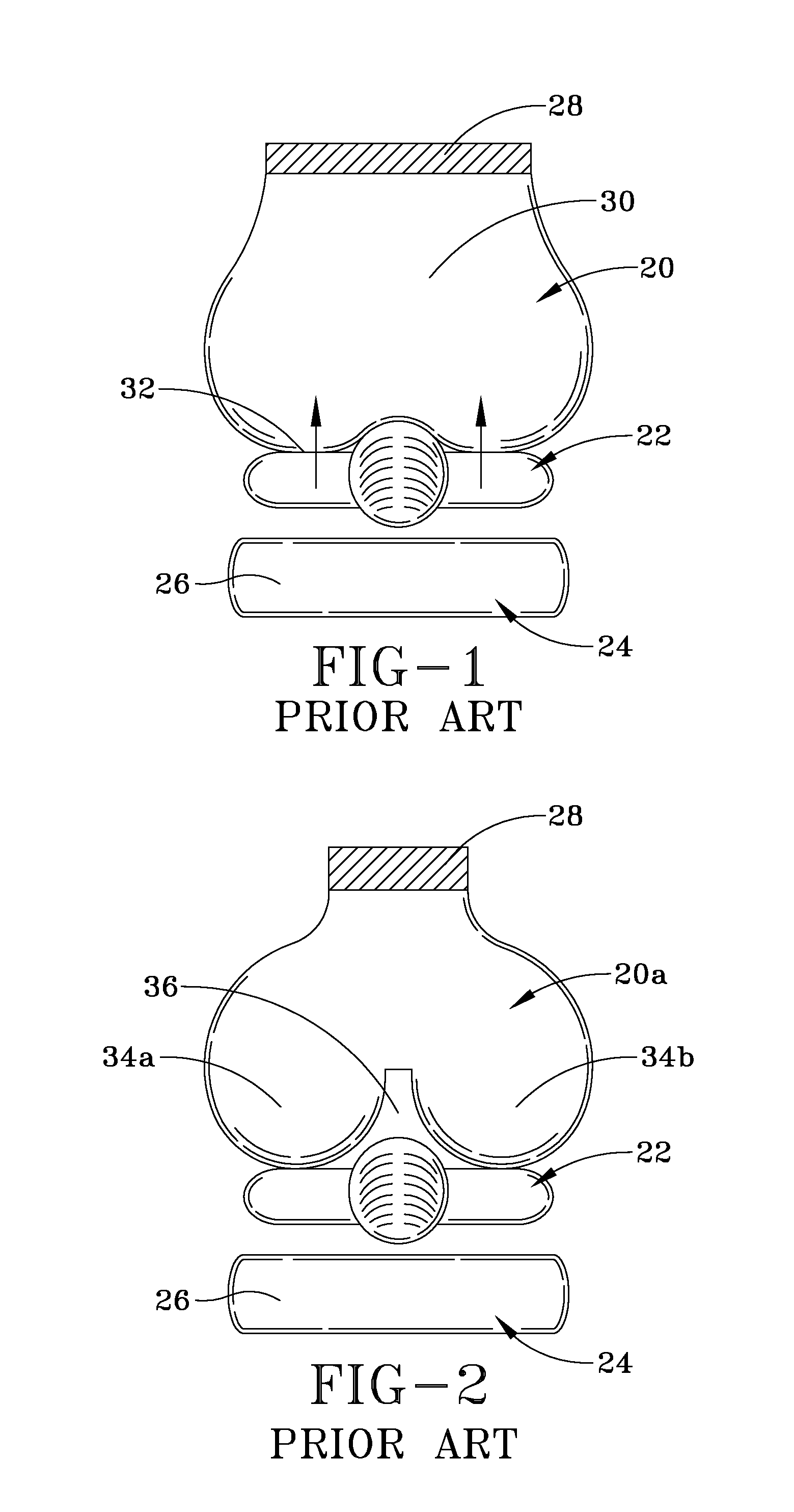
RELATED APPLICATIONS[0001]The present invention claims priority to provisional U.S. application 61 / 441,683 filed Feb. 11, 2011 entitled “Airbag cushion”.TECHNICAL FIELD[0002]The present invention relates to an improved airbag cushion having a recessed or groove portion preferably for the passenger side of vehicles.BACKGROUND OF THE INVENTION[0003]FIG. 1 illustrates a top view showing a deployed conventional prior art passenger side airbag 20 in relation to an occupant 22 seated on a seat 24. The seat back 26 is the only portion of the seat shown. Airbag 20 is inflated by an airbag inflator 28. Airbag 20 typically comprises a single inflatable chamber 30 inflated by gas from inflator 28. The face portion or panel 32 of the airbag impacts the occupant's chest, shoulders and head. As can be appreciated, as the occupant's seated position at the time of airbag inflation deviates from the normal seated position by taking a position closer to the vehicle's instrument panel, the velocity at...

Claims


Application Information

Patent Timeline
Patent Type & Authority Applications(United States)
IPC IPC(8): B60R21/16
CPCB60R21/231B60R21/235B60R21/2338
Inventor MALLINGER, HEATHERRASKA, MARYCURRY, LYLE
Owner KEY SAFETY SYST
Learn More