
Injection devices

a technology of injection device and stent, which is applied in the direction of infusion needle, closure cap, packaging, etc., can solve the problems of device firing unintentionally, cap easily being accidentally removed, etc., and achieve the effect of reducing the effective restricting and reducing the width of the slo

Active Publication Date: 2021-04-13
OWEN MUMFORD
View PDF11 Cites 0 Cited by
  • Summary
  • Abstract
  • Description
  • Claims
  • Application Information

AI Technical Summary

Benefits of technology

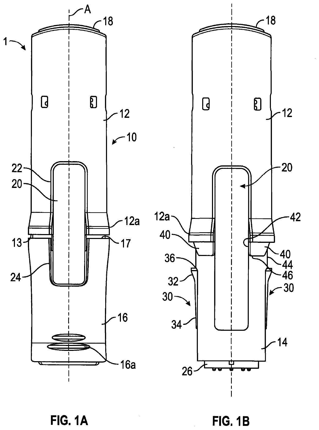
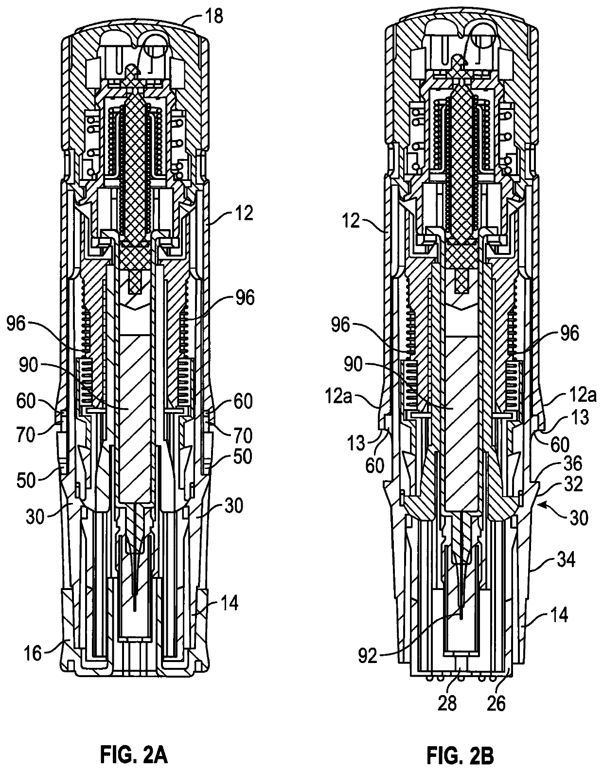
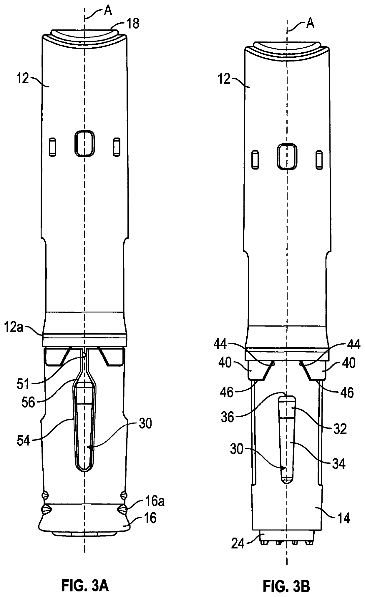
[0017]When cap is connected to the injection device in its fully rearward position the positioning of the engagement features within the cavity limits the outward movement of the side walls of the slot. In contrast when the cap is removed by a user it is pulled forwardly and the engagement features move out of the cavity to allow the side walls of the slot to displace outwardly. Further, if the cap moves rearwards, for example when the cap is subjected to a sudden shock load or impact, the forwarding facing mating surfaces of the cavity engage with the cap engagement features, and the two side walls of the slot are urged together and are prevented from moving outwardly or apart from each other. This means that the outwardly projecting protrusion is prevented from being released from the cap slot and the cap is held or retained on the housing.
[0027]Such an arrangement may advantageously ensure that a force urging the cap and housing together may wedge the resiliently deformable sides of the slot together, thereby reducing the width of the slot, and cause the cap to in effect grip the protrusion and hold the cap on the housing. This arrangement may prevent the cap from being accidentally or intentionally removed from the housing when a force is applied to the cap, for example, when an injection device is accidentally dropped on its forward end and the cap is urged towards the housing.
[0028]This arrangement may also advantageously ensure that an internal force generated within the housing pushing the cap forward may initially urge the rearward mating surfaces outwards towards the forward mating surfaces of the housing until the rearward mating surfaces contact and are restrained by the forward mating surfaces, thereby restricting the width of the slot and causing the cap in effect to grip the protrusion. This arrangement may prevent the cap from being accidentally or unintentionally removed from the housing when an impact or shock load is applied to a rear end or a trigger button of the device. For example, when an injection device is accidentally dropped on its rear end and a forward housing component comprising the outwardly projecting protrusion may be urged momentarily forward. This arrangement may also prevent the cap from being accidentally or unintentionally removed from the housing when an impact or shock load is applied to the device which is sufficient to cause inertial forces within the device which release an interlock within the housing. The resiliently deformable portions may define at least a rearward portion of the slot. The resiliently deformable portions may be cammed inwardly relative to the slot to reduce the effective width of the slot at the rearward end (or neck) of the slot.
[0049]The reduced diameter projections may be held in the undercuts when the cap is mounted. This prevents the front of rear body housing splaying outwardly and holds the mating surfaces of the cavity against the cap engagement surfaces.

Problems solved by technology

This type of arrangement only provides a reasonably light connection between the cap and injection device but the cap can easily be accidentally be removed, for example, when the device is dropped or banged against a surface, such as the floor.
This may be a particularly important issue with pressure activated injection devices, in which the user presses a forward portion of the device against the injection site to release a mechanical interlock and fire the device.
In pressure activation devices, a large impact can cause inertial forces within the device which release interlock and cause the device to fire unintentionally.

Method used


Image

  • Injection devices
  • Injection devices
  • Injection devices

Examples


Embodiment Construction

[0076]Front as used herein will be understood to refer to the end of the injector assembly (or components thereof) which, in use, are closest to the delivery needle delivery end of the injector (i.e. the end which is pointed at the skin). Rear as used herein will be understood to refer to the end of the pen injector assembly (or components thereof) which, in use, are furthest from the needle delivery end of the injector (i.e. the end which is pointed away from the skin). Forward and rearward will, likewise, be understood to refer to the directions orientated towards the front and rear of the injector assembly.

[0077]Axial, radial and circumferential are used herein to conveniently refer to the general directions relative to the longitudinal direction of the injection device (or components thereof). The skilled person will, however, appreciated that these terms are not intended to be narrowly interpreted (and for example, the injection device may have a non-circular and / or irregular f...


PUM


Abstract

The invention relates to an injection device comprising an elongate housing and a cap removably mounted over a forward end of the housing. The cap comprising at least one slot extending forwardly from its rear edge; the at least one slot being configured to engage with an outwardly projecting protrusion on an outer surface of the housing when the cap is mounted on the housing. A rearward portion of the cap includes rearwardly extending engagement features provided on each side of the at least one slot, the engagement features being configured to locate within a cavity in the housing when the cap is mounted on the housing. The cavity is provided with corresponding surfaces which align with the cap engagement features so as to hold the outwardly projecting protrusion within the cut-out.

Description

CROSS-REFERENCE TO RELATED APPLICATIONS[0001]This application represents the U.S. National Stage of International Application No. PCT / GB2016 / 050403 filed on Feb. 18, 2016, which is incorporated by reference in its entirety, and is based upon, claims priority to, and incorporates herein by reference in its entirety, United Kingdom Patent Application Serial No. GB 1507491.7, filed Apr. 30, 2015.FIELD OF THE INVENTION[0002]This invention relates to injection devices for delivering a dose of medicament from a syringe. In particular, but not exclusively the invention relates to an “autoinjector” device.BACKGROUND OF THE INVENTION[0003]Injection devices are used for the convenient administration of medicaments. For example, injection devices (which may typically be in the form of a pen injector) may be used for providing a single metered dose of a medicament, such as Epinephrine, in an emergency or for providing regular metered doses of a medicament, such as Insulin. Such devices may be e...

Claims


Application Information

Patent Timeline
Patent Type & Authority Patents(United States)
IPC IPC(8): A61M5/32A61M5/20A61M5/31
CPCA61M5/326A61M5/2033A61M5/3202A61M5/3204A61M2005/206A61M2005/2013A61M2005/3125A61M2005/3263A61M5/20A61M5/3134A61M5/3213B65D41/16
Inventor GOULD, OLIVERSHABUDIN, TAHIRFARMER, MATTHEW
Owner OWEN MUMFORD
Learn More