Vacuum chambers with shared pump

a technology of vacuum chambers and shared pumps, applied in the field of vacuum chambers, can solve the problems hardware costs and costs associated with the extra space requirements, and achieve the effect of increasing the overall cost of the system

Inactive Publication Date: 2012-09-06
APPLIED MATERIALS INC
View PDF9 Cites 174 Cited by
  • Summary
  • Abstract
  • Description
  • Claims
  • Application Information

AI Technical Summary

Benefits of technology

[0007]The present disclosure generally relates to vacuum chambers for processing substrates. The vacuum chambers include a first substrate chamber isolated from a second substrate chamber, a vacuum pump, and a high conductance foreline coupled to the pump. A high conductance pumping conduit couples the foreline to the first substrate chamber and a low conductance pumping conduit coupling the foreline to the second substrate chamber. The conductance of each conduit is selected to allow different pumping requirements of each chamber to be met using a single pump (or pumps) coupled to a single foreline.
[0008]Another embodiment of the present disclosure provides a chamber body having first and second substrate transfer chambers. The first substrate transfer chamber is isolated from the second substrate transfer chamber. The substrate transfer chambers further include a vacuum pump and a high conductance foreline coupled to the pump. A high conductance pumping conduit couples the foreline to the first substrate transfer chamber, and a low conductance pumping conduit couples the foreline to the second substrate transfer chamber.
[0009]Another embodiment of the present disclosure provides a system having a first chamber body having a first substrate transfer chamber isolated from a second first substrate transfer chamber and a second chamber body having a third substrate transfer chamber isolated from a fourth first substrate transfer chamber. The system also includes a vacuum pump, a high conductance foreline coupled to the pump, a first high conductance pumping conduit coupling the high conductance foreline to the first substrate transfer chamber, and a second high conductance pumping conduit coupling the high conductance foreline to the third substrate transfer chamber. The system further includes a low conductance foreline coupled to the high conductance foreline, a first low conductance pumping conduit coupling the low conductance foreline to the second substrate transfer chamber, and a second low conductance pumping conduit coupling the low conductance foreline to the fourth substrate transfer chamber.

Problems solved by technology

Thus, vacuum pumps are only conventionally shared between vacuum chambers having identical pumping requirements due to the inability to precisely meet pumping requirements which are unique to different environments.
The need for dedicated pumps for each vacuum chamber increases the overall cost of the system, as well as hardware costs and costs associated with the extra space requirements for multiple pumps.

Method used


Image

  • Vacuum chambers with shared pump
  • Vacuum chambers with shared pump
  • Vacuum chambers with shared pump

Examples


Embodiment Construction

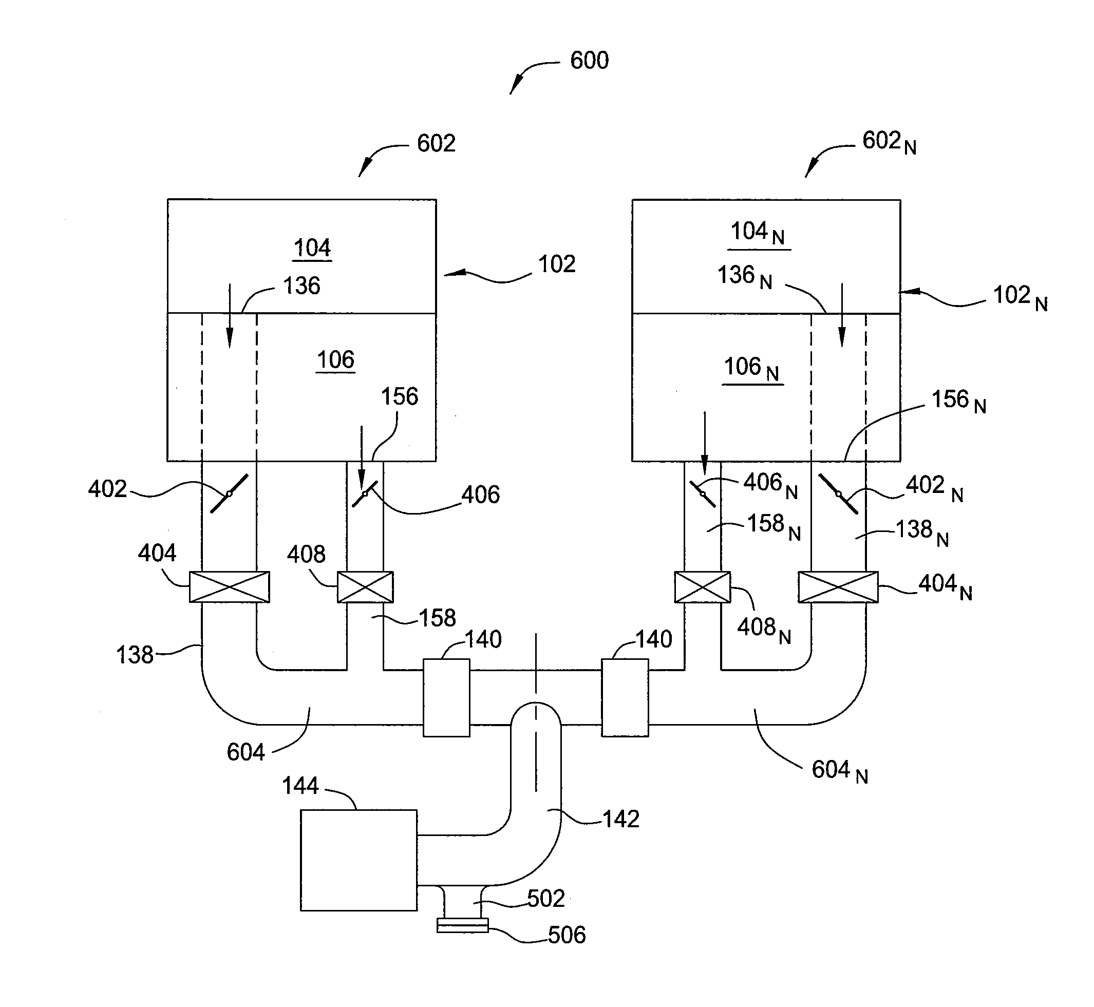
[0019]The present disclosure provides a substrate vacuum processing system that includes a plurality of substrate chambers isolated from each other. The substrate chambers are each coupled to a vacuum pump by pumping conduits configured to have a ratio of conductance selected so that the substrate chambers may share a common vacuum pump.

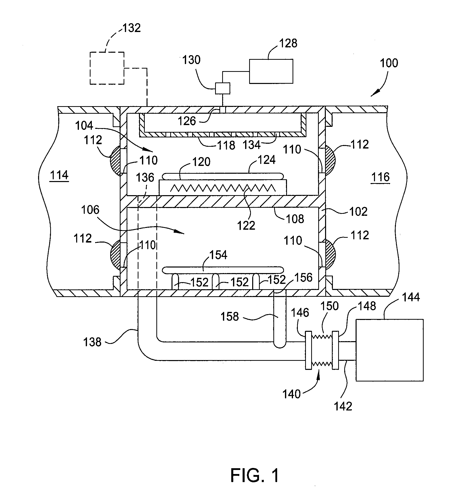
[0020]FIG. 1 is a front sectional view of a processing system 100 according to one embodiment of the disclosure. The processing system 100 generally includes a chamber body 102 having a first chamber 104 isolated from a second chamber 106 by an internal wall 108. Although the chambers 104, 106 are illustrated in a common chamber body 102, the chambers 104, 106 may alternatively be disposed in separate bodies. Substrate transfer ports 110 formed through the chamber body 102 provide access to the first and second chambers 104, 106. Doors 112 coupled to the chamber body 102 operate to selectively open and close each substrate transfer port 110 to facili...


PUM

PropertyMeasurementUnit
conductanceaaaaaaaaaa
pressureaaaaaaaaaa
vacuumaaaaaaaaaa

Abstract

Embodiments of the present disclosure generally relate to vacuum processing chambers having different pumping requirements and connected to a shared pumping system through a single foreline. In one embodiment, the vacuum processing chambers include a high conductance pumping conduit and a low conductance pumping conduit coupled to a single high conductance foreline. In another embodiment, a plurality of unbalanced chamber groups may be connected to a common pumping system by a final foreline.

Description

CROSS-REFERENCE TO RELATED APPLICATIONS[0001]This application claims benefit of U.S. Provisional Patent Application Ser. No. 61 / 448,024, filed Mar. 1, 2011, which is herein incorporated by reference.BACKGROUND[0002]1. Field[0003]Embodiments of the present disclosure generally relate to vacuum chambers having different pumping requirements coupled to a pumping system through a single foreline.[0004]2. Description of the Related Art[0005]In vacuum processing tools such as those used to fabricate integrated circuits, flat panel displays, and magnetic media among others, a vacuum environment is maintained in the chambers of the vacuum processing tools through the use of a vacuum pump. Since the processes performed in the various vacuum processing chambers have different pressure and / or pumping requirements, each vacuum processing chamber typically has a dedicated vacuum pump. Thus, vacuum pumps are only conventionally shared between vacuum chambers having identical pumping requirements ...

Claims


Application Information

Patent Timeline
Patent Type & Authority Applications(United States)
IPC IPC(8): C23C16/455B05C11/00C23C16/50B05C5/02B05B1/18
CPCC23C16/4412H01L21/02
Inventor PAL, ANIRUDDHASALINAS, MARTIN JEFFREYLEE, JARED AHMADREUTER, PAUL B.YOUSIF, IMAD
Owner APPLIED MATERIALS INC
Why Eureka
Try Eureka