

Coupler device
- Summary
- Abstract
- Description
- Claims
- Application Information
AI Technical Summary
Benefits of technology
Problems solved by technology
Method used
Image

Examples
Embodiment Construction
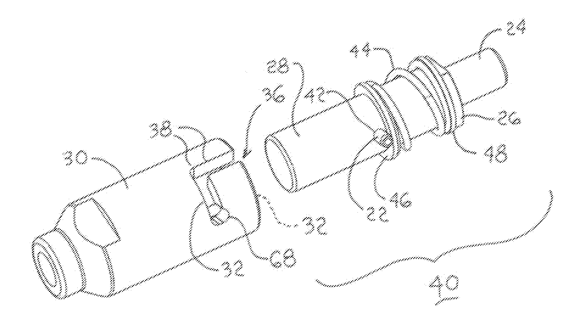
[0018]The following detailed description is of the best currently contemplated modes of carrying out the invention. The description is not to be taken in a limiting sense, but is made merely for the purpose of illustrating the general principles of the invention. A coupler assembly is disclosed, suitable for use in quickly and rigidly coupling and uncoupling a removable device to a support structure, wherein the disclosed coupler assembly is designed without internal ball bearings or an internal spring, so at to overcome conventional contamination and failure problems. Accordingly, the disclosed coupler assembly not only eliminates contamination from being trapped between coupler components, but is also is easily cleaned by the user. Moreover, the disclosed coupler assembly functions to mitigate vibration between coupled parts by using an external compression spring to provide a pre-load at the coupling junction.
[0019]Certain terminology may be used in the following description for ...
PUM
| Property | Measurement | Unit |
|---|---|---|
| diameter | aaaaa | aaaaa |
| diameter | aaaaa | aaaaa |
| force | aaaaa | aaaaa |
Abstract
Description
Claims
Application Information