Directional planar spiral antenna

Active Publication Date: 2012-09-13
ANTENNASYS
View PDF5 Cites 16 Cited by
  • Summary
  • Abstract
  • Description
  • Claims
  • Application Information

AI Technical Summary

Benefits of technology

[0014]One such embodiment includes a directional planar spiral antenna of any type including a log-spiral slot antenna having a feed-point configured to transfer energy to and from the spiral antenna along current paths as one skilled in the art will appreciate. The antenna may have an antenna impedance that in one or more embodiments is 150 Ohms. The embodiment further includes an energy absorbent backing and an energy absorbent siding cou

Problems solved by technology

Some buildings are difficult to receive cell phone coverage in.
Current implementations of microcells suffer from the types of antennas that are utilized.
Attempts at absorbing rearward pointing energy in order to make a directional antenna have been less than optimal in that known directional implementations still have sizable back lobes.
This means that in the case of a BDA, the antenna pointing into the building would still have

Method used


Image

  • Directional planar spiral antenna
  • Directional planar spiral antenna
  • Directional planar spiral antenna

Examples


Embodiment Construction

[0083]A directional planar spiral antenna will now be described. In the following exemplary description numerous specific details are set forth in order to provide a more thorough understanding of the ideas described throughout this specification. It will be apparent, however, to an artisan of ordinary skill that embodiments of ideas described herein may be practiced without incorporating all aspects of the specific details described herein. In other instances, specific aspects well known to those of ordinary skill in the art have not been described in detail so as not to obscure the disclosure. Readers should note that although examples of the innovative concepts are set forth throughout this disclosure, the claims, and the full scope of any equivalents, are what define the invention.

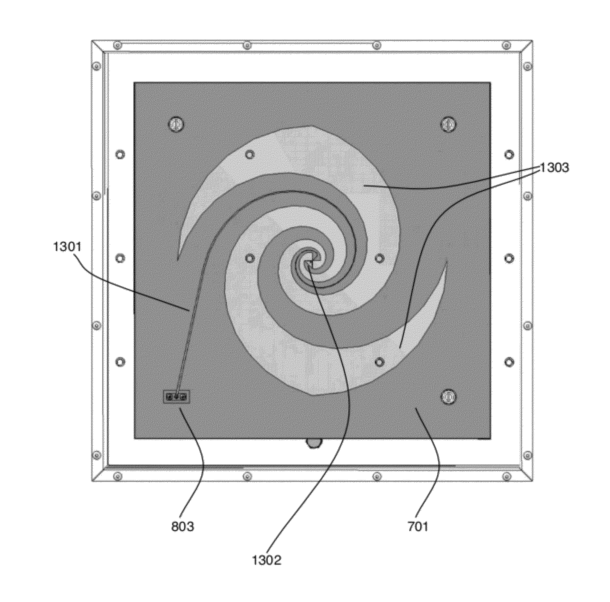
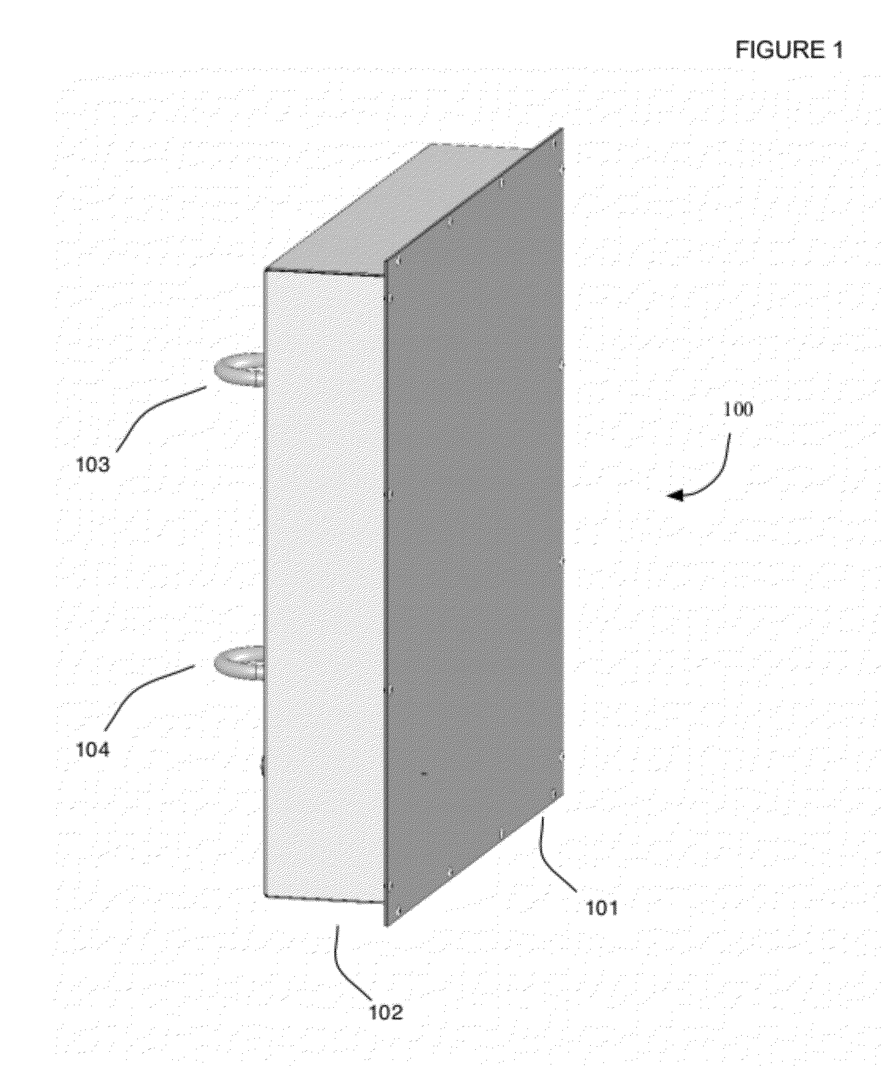
[0084]FIG. 1 shows a side perspective view of an embodiment of a directional planar log-spiral slot antenna 100. Any type of spiral may be utilized. Covering the antenna is radome 101, that in one or m...


PUM


Abstract

Directional wide band antenna that may be utilized to enhance cell phone coverage within a building, and/or for signals intelligence collection (SIGINT). Includes a spiral antenna with feed-point configured to transfer energy to/from the antenna. Includes an energy absorbent backing and an energy absorbent siding coupled with the spiral antenna. Includes a cavity behind the log-spiral slot antenna and in front of the energy absorbent backing. Includes a cable connector coupled to a tapered microstrip line coupled to the feed-point wherein the tapered microstrip line is configured to transform the input impedance to the antenna impedance. Housed in a container configured to hold the above listed components. Energy absorbent siding, cavity and energy absorbent backing greatly reduces back lobes. Another embodiment has log-spiral shaped slots at an outer portion of the log-spiral slot antenna overlap with the energy absorbent siding and wherein the feed-point overlaps the cavity.

Description

[0001]This application is a continuation in part of U.S. Utility patent application Ser. No. 12 / 544,838 filed 20 Aug. 2009, the specification of which is hereby incorporated herein by reference.BACKGROUND OF THE INVENTION[0002]1. Field of the Invention[0003]One or more embodiments setting forth the ideas described throughout this disclosure pertain to the field of antennas. More particularly, but not by way of limitation, one or more aspects of the disclosure enable a directional planar spiral antenna, for example Archimedean spiral, square spiral, star spiral, log-spiral or any other type of spiral antenna which may also be configured as a spiral arm or spiral slot antenna.[0004]2. Description of the Related Art[0005]Some buildings are difficult to receive cell phone coverage in. In order to provide cell phone coverage in these buildings, “microcells” have been installed to accommodate cell phone calls within these buildings. Microcells are implemented as low power cell instances i...

Claims


Application Information

Patent Timeline
IPC IPC(8): H01Q1/36
CPCH01Q1/007H01Q1/38H01Q17/001H01Q13/106H01Q13/18H01Q9/27
Inventor WEBB, SPENCER
Owner ANTENNASYS
Why Eureka
Try Eureka