Method and apparatus for improving antenna radiation patterns

a radiation pattern and antenna technology, applied in the field of antenna apparatus, can solve the problems of more interference to the service region of other base stations, two signals of the same channel arriving at a mobile station from different base stations, and unwanted back lobe of the antenna radiation pattern of the sector antenna, so as to improve the antenna radiation pattern of the base station, the effect of improving the antenna radiation pattern

Inactive Publication Date: 2006-07-25
NAT TAIWAN UNIV OF SCI & TECH
View PDF6 Cites 17 Cited by
  • Summary
  • Abstract
  • Description
  • Claims
  • Application Information

AI Technical Summary

Benefits of technology

[0013]Accordingly, the invention uses the electromagnetic scattering principle to design electromagnetic scattering structures configured on a radome of an antenna to improve the antenna radiation patterns. The material of the electromagnetic structure is conductive. According to the electromagnetic principles, when electromagnetic waves illuminate conductive materials, induced currents will be excited on the conductive materials. Therefore, currents will be induced on the electromagnetic scattering structures due to the electromagnetic waves from the base-station antenna, and the induced currents then generate secondary radiation electromagnetic waves. The secondary radiation electromagnetic waves will interfere with the electromagnetic waves from the base-station antenna, and thus improve the antenna radiation patterns of the base station.
[0014]It is therefore an objective of the present invention to provide a method for improving antenna radiation patterns, which effectively reduces the back lobe of the antenna radiation patterns, to decrease the energy radiating to areas not covered by the base station, and mitigate interferences between adjacent base stations.
[0015]It is another objective of the present invention to provide a method for improving antenna radiation patterns in the horizontal plane, of which the energy outside the service region is reduced to mitigate the co-channel interferences or the adjacent-channel Interferences between the base stations. Or, the service region is increased to enlarge the coverage area of the base station.

Problems solved by technology

However, in practice, the antenna radiation pattern of the sector antenna has an unwanted back lobe that radiates energy backward to other cells.
Since a cellular system adopts the above-mentioned frequency reuse technique, two signals of the same channel arriving at a mobile station from different base stations will interfere with each other.
Thus, a larger back lobe of the base-station antenna radiation pattern will cause more interference to the service regions of other base stations.
Therefore, the back lobe radiations will more likely cause co-channel interferences to adjacent base stations assigned with the same frequencies.
However, this solution reduces the quantity of base stations in a certain area, and decreases the signal strengths over some regions in the certain area.
However, this conventional method would affect the outer appearance of the base station, increase the wind resistance of the base-station antenna, require higher cost, need more construction efforts, and yet only provide smaller improvement.
Thus, one may replace the metal-grid panel, which is more expensive, hard to construct, and only a smaller improvement.

Method used


Image

  • Method and apparatus for improving antenna radiation patterns
  • Method and apparatus for improving antenna radiation patterns
  • Method and apparatus for improving antenna radiation patterns

Examples


first embodiment

The First Embodiment

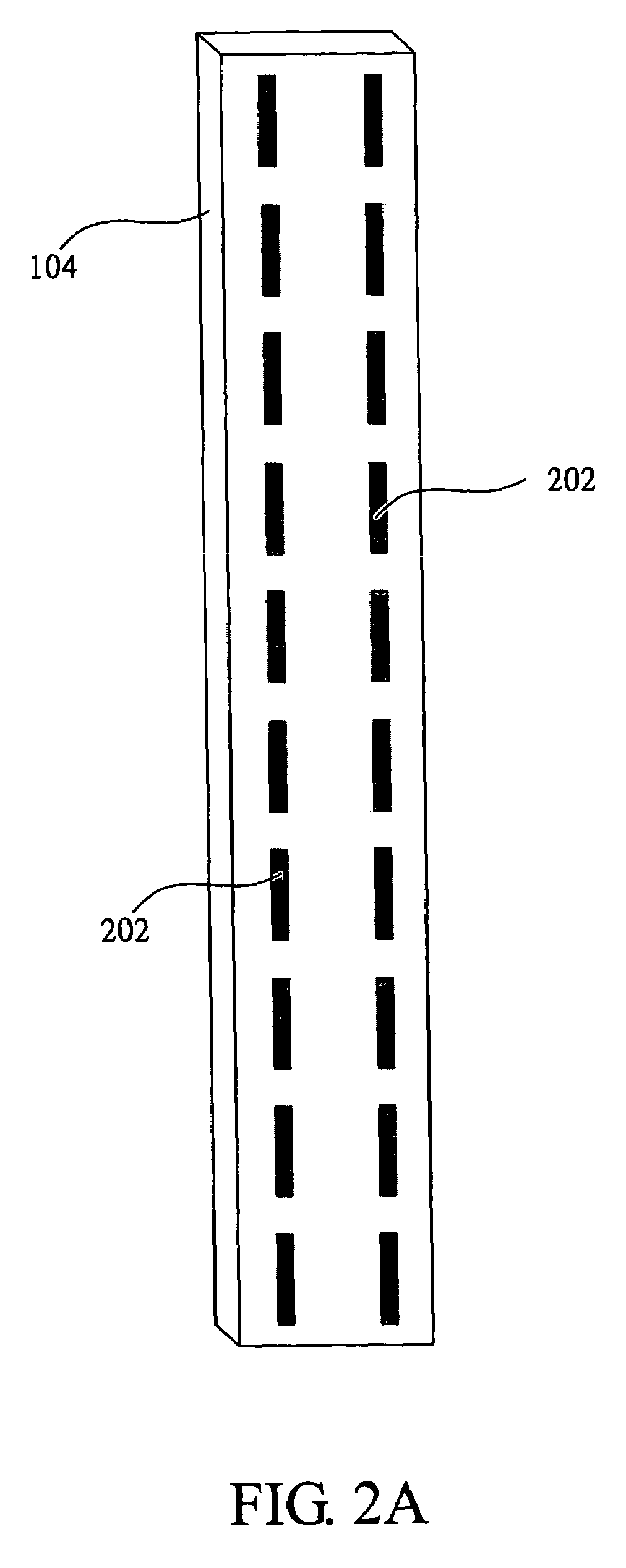
[0061]FIG. 2A illustrates a schematic view of the first embodiment of the present invention. In this embodiment, the electromagnetic scattering structure comprises a plurality of strip units 202. The length of the strip unit 202 is half of the corresponding wavelength at the central working frequency, which is about 76 mm, and the width of the strip unit 202, which is not critical, is 2 mm in this embodiment. The strip units 202 are arranged periodically in two rows and in front of the antenna inside the radome 104 (i.e. the array antenna 102 as illustrated in FIG. 1). The two rows are configured on the surface of the radome 104, and each is spaced a quarter wavelengths from each closer edge of the radome 104.

[0062]FIG. 2B illustrates far-field antenna radiation patterns in the horizontal plane of the first embodiment, and the radial axis thereof represents the relative field value in dB. The curve 222 is the antenna radiation pattern without the electromagnetic ...

second embodiment

The Second Embodiment

[0064]FIG. 3A illustrates a schematic view of the second embodiment of the present invention. In this embodiment, the electromagnetic scattering structure comprises two strip units 302. The length of the strip unit 302 is the same as the length of the radome 104, and the width of the strip unit 302, which is not critical, is 2 mm in this embodiment. The two strip units 302 are in front of the antenna inside the radome 104 (i.e. the array antenna 102 as illustrated in FIG. 1), and are configured on the surface of the radome 104

[0065]FIG. 3B illustrates far-field antenna radiation patterns in the horizontal plane of the second embodiment, and the radial axis thereof represents the relative field value in dB. The curve 322 is the antenna radiation pattern without the electromagnetic scattering structure of the embodiment, and the curve 324 is the antenna radiation pattern of the antenna with the electromagnetic scattering structure. FIG. 3C illustrates far-field an...

third embodiment

The Third Embodiment

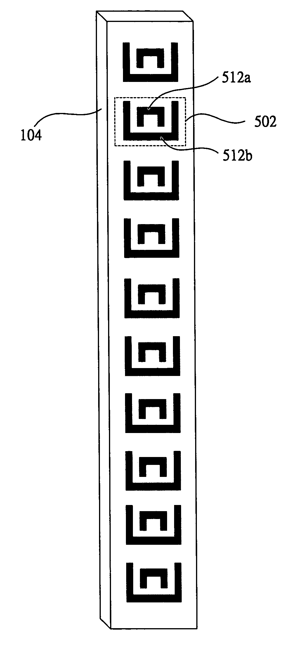
[0067]FIG. 4A illustrates a schematic view of the third embodiment of the present invention. In this embodiment, the electromagnetic scattering structure comprises a plurality of cross units 402. Each of the cross units 402 has two strip portions 412a and 412b with identical lengths. The length of the strip portions 412a and 412b is a half the corresponding wavelength at the central working frequency, and the widths of the strip portions 412a and 412b, which are not critical, are both 2 mm in this embodiment. The cross units 402 are in front of the antenna inside the radome 104 (i.e. the array antenna 102 as illustrated in FIG. 1), and are configured in two rows interleaving on the surface of the radome 104.

[0068]FIG. 4B illustrates far-field antenna radiation patterns in the horizontal plane of the third embodiment, and the radial axis thereof represents the relative field value in dB. The curve 422 is the antenna radiation pattern without the electromagnetic sc...


PUM


Abstract

Several electromagnetic scattering structures are designed to improve antenna radiation patterns. The electromagnetic scattering structure has a conductive layer with certain patterns, and is applied on the radome of the base-station sector antenna. The electromagnetic waves radiating from the antenna therein induce scattering effects, which, together with the electromagnetic diffractions from the rear metal panel of the antenna, can substantially reduce the back lobe and the fields in regions not covered by the antenna. Thus, the antenna radiation patterns are improved so that a lower possibility of co-channel interferences between adjacent base stations can be achieved and therefore better efficiency of the base-station coverage also can be obtained.

Description

RELATED APPLICATION[0001]The present application is based on, and claims priority from, Taiwanese Application Ser. No. 92126026, filed Sep. 19, 2003, the disclosure of which is herein incorporated by reference herein in its entirety.BACKGROUND[0002]1. Field of Invention[0003]The present invention relates to an antenna apparatus. More particularly, the present invention relates to method and apparatus for improving antenna radiation patterns.[0004]2. Description of Related Art[0005]Mobile telephones are portable and wireless telephone devices installed on conveyances, such as vehicles and ships, or carried by a user. Mobile telephones are different from wireless extensions of the wired telephones or long distance radio transceivers. Mobile telephones provide users with the benefits of the same functions of and greater convenience than wired telephones. Connecting with international direct dialing, mobile telephone users can communicate with any other person in the world within covera...

Claims


Application Information

Patent Timeline
Patent Type & Authority Patents(United States)
IPC IPC(8): H01Q1/42H01Q1/24H01Q1/38H01Q19/00
CPCH01Q1/246H01Q19/005H01Q1/42H01Q1/38
Inventor WU, CHENG-HSIUNGYANG, CHANG-FA
Owner NAT TAIWAN UNIV OF SCI & TECH
Why Eureka
Try Eureka