Subreflector of a dual-reflector antenna

a dual-reflector, sub-reflector technology, applied in the direction of antennas, electrical equipment, etc., can solve the problems of reducing the front-to-back ratio of the antenna, environmental pollution through rf waves, and high spillover losses, so as to reduce the cost of the dielectric material part, facilitate design, and small in siz

Active Publication Date: 2014-12-18
ALCATEL LUCENT SAS
View PDF5 Cites 10 Cited by
  • Summary
  • Abstract
  • Description
  • Claims
  • Application Information

AI Technical Summary

Benefits of technology

[0030]The main idea is to construct the subreflector from two parts in order to facilitate design and lower the cost of the dielectric material part. The part made of dielectric material, for example a plastic material such as “Rexolite”, is small in size and has a special profile. This dielectri

Problems solved by technology

These antennas exhibit high spillover losses and decrease the antenna's front-to-back ratio.
Overflow losses lead to environmental pollution through RF waves and must be limited to levels defined by standards.
The

Method used


Image

  • Subreflector of a dual-reflector antenna
  • Subreflector of a dual-reflector antenna
  • Subreflector of a dual-reflector antenna

Examples


Embodiment Construction

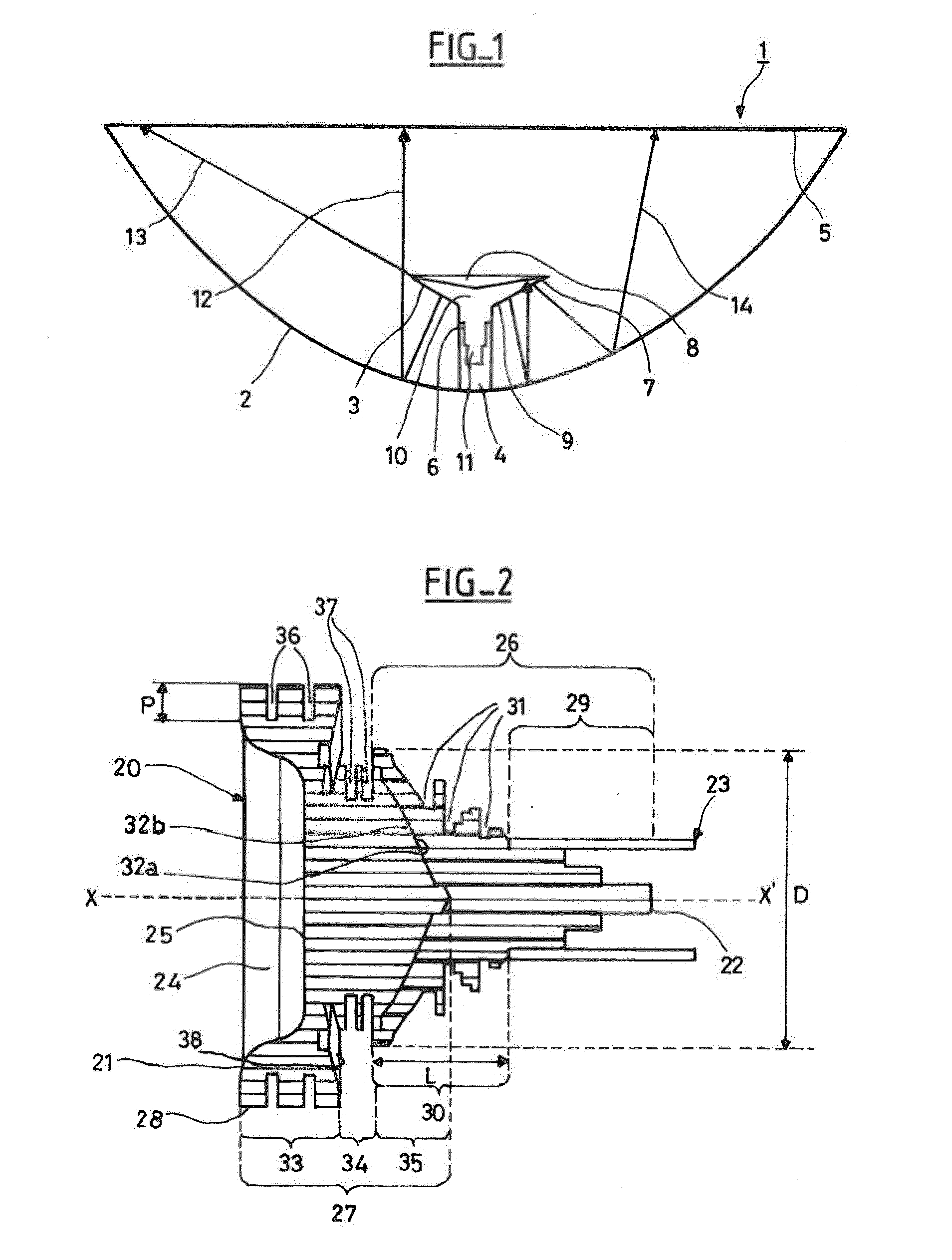
[0041]FIG. 1 illustrates an antenna 1 of a known type with a deep-dish reflector and low focal distance, comprising a primary reflector 2 and a subreflector 3. The antenna 1 is fed by a waveguide 4 which may be a hollow metal tube, for example one made of aluminum. The reflectors 2, 3 are protected by a radome 5. The subreflector 3 comprises a first extremity 6 with a lower radius making the junction with the waveguide 4 and one large-radius open extremity 7, where a convex inner surface 8, which reflects RF signals, meets an outer surface 9 that connects the two ends 6, 7. The outer surface 9 of the sub-reflector 3 is the surface facing the primary reflector 2. The inner surface 8 and the outer surface 9 are surfaces revolving around a single axis of revolution. A dielectric body 10 extends between the first and second ends 6, 7, limited by the inner surface 8 and the outer surface 9. Part 11 of the material of the dielectric body 10 extends to penetrate into the waveguide 4, in or...


PUM


Abstract

A subreflector of a dual-reflector antenna comprises a first extremity comprising a convex inner surface, a second extremity adapted for coupling to the extremity of a waveguide, and a body extending between the first extremity and the second extremity. The body comprises a first dielectric part having a portion penetrating into the waveguide and a portion outside the waveguide, and a second metallic part comprising a first cylindrical portion, contiguous with the first extremity of the subreflector, whose diameter is greater than the portion outside the waveguide of the first dielectric part, and a second cylindrical portion, adjacent to the first cylindrical portion, extended by a conical portion that penetrates into the first dielectric part. The first cylindrical portion features a flat ring-shaped surface that forms an angle less than 90° with the axis of the subreflector so as to face the primary reflector.

Description

CROSS-REFERENCE[0001]This application is based on French Patent Application No. 12,50,895 filed on Jan. 31, 2012, the disclosure of which is hereby incorporated by reference thereto in its entirety, and the priority of which is hereby claimed under 35 U.S.C. §119.BACKGROUND[0002]The present invention pertains to a dual-reflector antenna, particularly a microwave antenna normally used for mobile telecommunications networks.[0003]In order to create a more compact system, one utilizes dual-reflector antennas, in particular those of the Cassegrain type. The dual reflector comprises a primary concave reflector, most commonly parabolic, and a secondary convex reflector, of much lesser diameter, placed in the vicinity of the focus of the parabola on the same axis of revolution as the primary reflector. A feed device comprising a waveguide is located along the antenna's axis of symmetry, facing the subreflector. These antennas are so-called “deep dish” antennas with a low F / D ratio, less th...

Claims


Application Information

Patent Timeline
IPC IPC(8): H01Q15/14
CPCH01Q15/14H01Q19/026H01Q19/134H01Q19/193
Inventor TUAU, DENISLEBAYON, ARMEL
Owner ALCATEL LUCENT SAS
Why Eureka
Try Eureka