Difference coplanar waveguide UWB (Ultra Wide Band) wide slot trapped wave antenna with high attenuation band characteristic

A coplanar waveguide and notch antenna technology, applied in slot antennas, radiating element structures, circuits, etc., can solve the problem that the antenna does not use the coplanar waveguide feeding method, the antenna radiation pattern is not very ideal, and the notch squareness It is not very good, etc., to achieve the effect of low cost, simple structure and good radiation pattern

Inactive Publication Date: 2014-03-12
SOUTH CHINA UNIV OF TECH
View PDF4 Cites 10 Cited by
  • Summary
  • Abstract
  • Description
  • Claims
  • Application Information

AI Technical Summary

Problems solved by technology

But the squareness of the notch is not very good, and the frequency of the notch is not easy to control, and the radiation pattern of the antenna is not very ideal. Its structure is as follows: figure 1 shown
[0007] 2) In 2012, Li Li, Jing Yang, Xinwei Chen, Xiaowei Zhang and others published an article titled "Ultra-Wideband Differential Wide-Slot Antenna With Improved Radiation Patterns and Gain" in "IEEE TRANSACTIONS ON ANTENNAS AND PROPAGATION", The differential microstrip line feeding method is adopted, and the wide slot is fed by the symmetrical radiation patch to realize an ultra-wide frequency band. Compared with the traditional single-port antenna, the differential UWB antenna achieves good radiation in the entire frequency band pattern and good gain, but the antenna in this article does not adopt the coplanar waveguide feeding method, nor does it realize the notch characteristic, and its structure is as follows figure 2 and image 3 shown

Method used


Image

  • Difference coplanar waveguide UWB (Ultra Wide Band) wide slot trapped wave antenna with high attenuation band characteristic
  • Difference coplanar waveguide UWB (Ultra Wide Band) wide slot trapped wave antenna with high attenuation band characteristic
  • Difference coplanar waveguide UWB (Ultra Wide Band) wide slot trapped wave antenna with high attenuation band characteristic

Examples


Embodiment 1

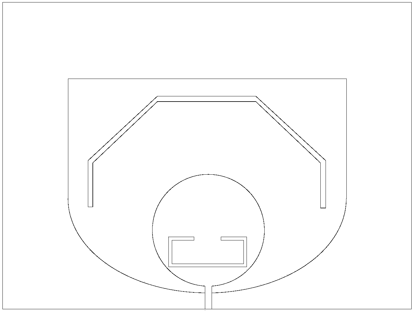
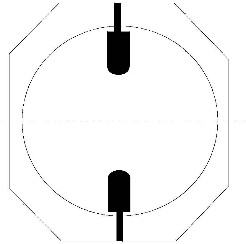
[0031] Such as Figure 4 and Figure 5 As shown, the differential coplanar waveguide UWB wide-slot trap antenna with high stopband characteristics of this embodiment includes a dielectric substrate, and the front side of the dielectric substrate is provided with a first feed circuit, a second feed circuit and a wide slot The ground structure 1, the first feeding circuit and the second feeding circuit are left and right symmetrical to form a differential coplanar waveguide feeding structure; the first feeding circuit includes a first feeding port 2, a first microstrip feeder 3, The first radiator 4 and the first via 5, the second feed circuit includes a second feed port 6, a second microstrip feeder 7, a second radiator 8 and a second via 9, the first The radiator 4 is connected to the first feeding port 2 through the first microstrip feeder 3, and the second radiator 8 is connected to the second feeding port 6 through the second microstrip feeder 7; the wide gap ground struct...


PUM


Abstract

The invention discloses a difference coplanar waveguide UWB (Ultra Wide Band) wide slot trapped wave antenna with a high attenuation band characteristic. The difference coplanar waveguide UWB wide slot trapped wave antenna comprises a dielectric substrate, wherein a first feed circuit, a second feed circuit and a wide slot ground structure are arranged on the front face of the dielectric substrate; the first feed circuit and the second feed circuit are in bilateral symmetry to form a difference coplanar waveguide feed structure; the first feed circuit comprises a first feed port, a first micro-strip feed wire and a first radiating body; the second feed circuit comprises a second feed port, a second micro-strip feed wire and a second radiating body; the first radiating body is connected with the first feed port by the first micro-strip feed wire; the second radiating body is connected with the second feed port by the second micro-strip feed wire; a first resonance branch knot and a second resonance branch knot are respectively arranged on the upper part and the lower part of the inner side of a polygonal wide slot on the wide slot ground structure; the first and second resonance branch knots are vertically symmetrical. The antenna is simple in structure and is capable of realizing a trapped wave function.

Description

technical field [0001] The invention relates to a differential coplanar waveguide UWB wide-slot trap antenna, in particular to a differential coplanar waveguide UWB wide-slot trap antenna with high stop band characteristics, belonging to the field of wireless communication. Background technique [0002] With the development of wireless communication technology, wireless communication systems have increasingly strong demands on the miniaturization and high integration of radio frequency devices. At present, RF circuits usually use differential technology to transmit signals, and many RF front-end devices can be directly integrated into transceiver chips. However, as an important component of the RF front-end circuit, most antennas are designed as single-port devices and cannot be directly integrated with differential circuits. Usually, a balun is required to convert the differential signal into a single-port signal and then feed it into the antenna. The use of the balun will...

Claims


Application Information

Patent Timeline
Patent Type & Authority Applications(China)
IPC IPC(8): H01Q1/36H01Q13/10
Inventor 李文翱涂治红褚庆昕
Owner SOUTH CHINA UNIV OF TECH
Why Eureka
Try Eureka