Antenna For Increasing Beamwidth Of An Antenna Radiation Pattern

a radiation pattern and antenna technology, applied in the field of antennas, can solve the problems of unsuitable antenna array for satellite digital audio radio service (sdars) applications, unsatisfactory configuration of the antenna array of the '455 publication, and inability to transmit circularly polarized rf signals, etc., to prevent the abrupt discontinuity of the rf signal, reduce undesired diffraction effects, and prevent the effect of abrupt discontinuity

Inactive Publication Date: 2012-01-26
AGC AUTOMOTIVE AMERICAS
View PDF4 Cites 9 Cited by
  • Summary
  • Abstract
  • Description
  • Claims
  • Application Information

AI Technical Summary

Benefits of technology

[0005]The invention provides an antenna comprising a ground plane, a dielectric, an active radiating element, a feeding element, and a passive radiating element. The dielectric is disposed on the ground plane, and the active radiating element is embedded in the dielectric for transmitting and / or receiving an RF signal. The feeding element extends into the dielectric and is electrically coupled to the active radiating element. The passive radiating element is disposed on the ground plane and surrounds a periphery of the dielectric. The passive radiating element perturbates the RF signal. The ground plane has a plurality of edges. At least one of the edges extends as a curvilinear lip in a direction opposite the passive radiating element. The edge or edges which extend as a curvilinear lip direct the RF signal and prevent abrupt discontinuity of the RF signal.
[0006]The RF signal follows the curvilinear lip of the ground plane thereby preventing the abrupt discontinuity of the RF signal and reducing undesired diffraction effects which would, ultimately, have an impact on a beamwidth of an antenna radiation pattern of the antenna. As such, the edges of the ground plane, at least one of which extends as a curvilinear lip, enable this antenna to improve reception characteristics of an SDARS signal at low elevation angles, generally those ranging from 10° to 30° and from 150° to 170°. Additionally, the passive radiating element which, as described above, perturbates the RF signal, acts in conjunction with the edge of the ground plane to further improve the beamwidth the antenna radiation pattern.

Problems solved by technology

The construct of the antenna array of the '455 publication is not ideal for transmission and / or reception of circularly polarized RF signals.
Therefore, this antenna array is not appropriate for Satellite Digital Audio Radio Service (SDARS) applications, and there is a need for an improved antenna.

Method used


Image

  • Antenna For Increasing Beamwidth Of An Antenna Radiation Pattern
  • Antenna For Increasing Beamwidth Of An Antenna Radiation Pattern
  • Antenna For Increasing Beamwidth Of An Antenna Radiation Pattern

Examples


Embodiment Construction

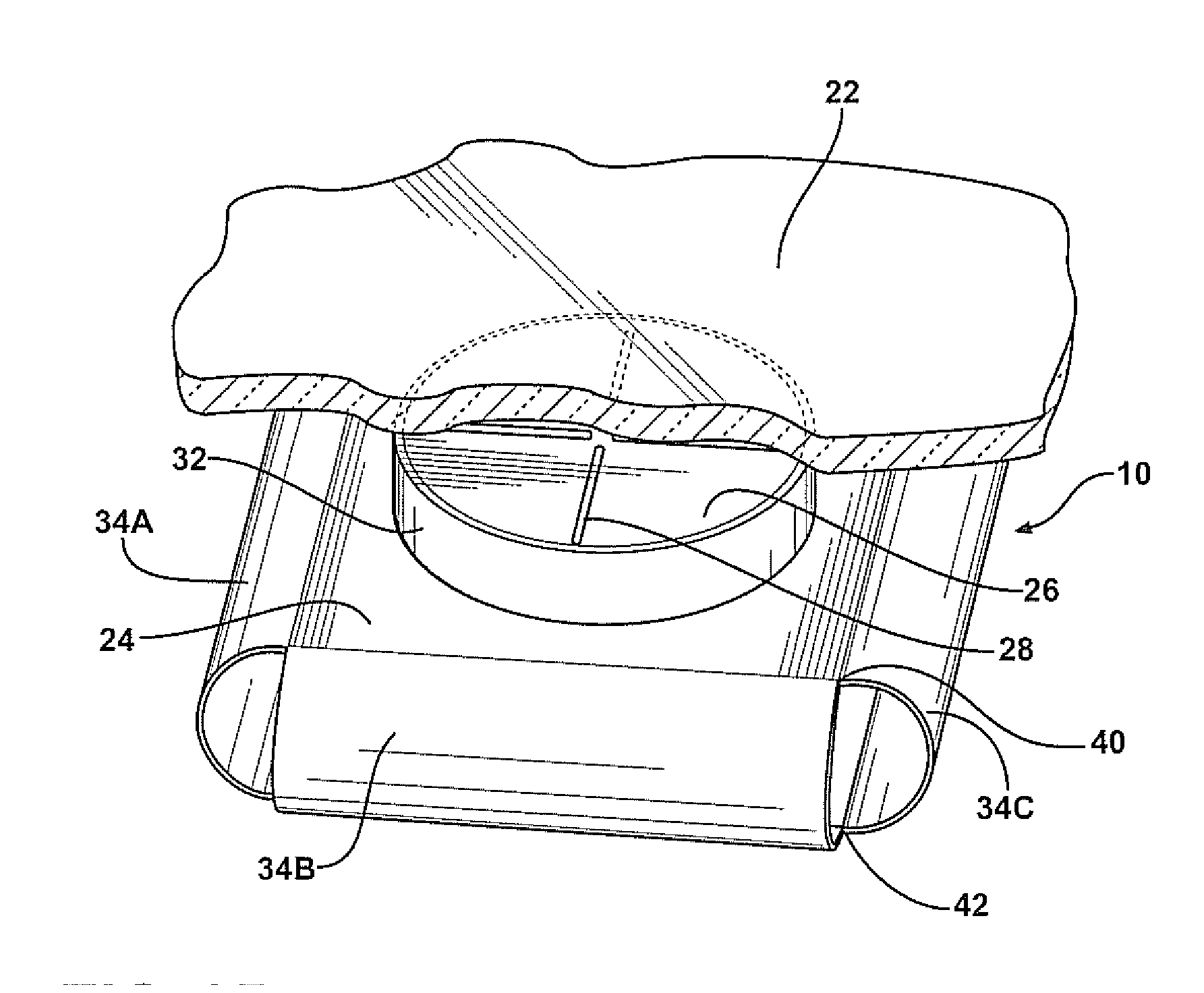
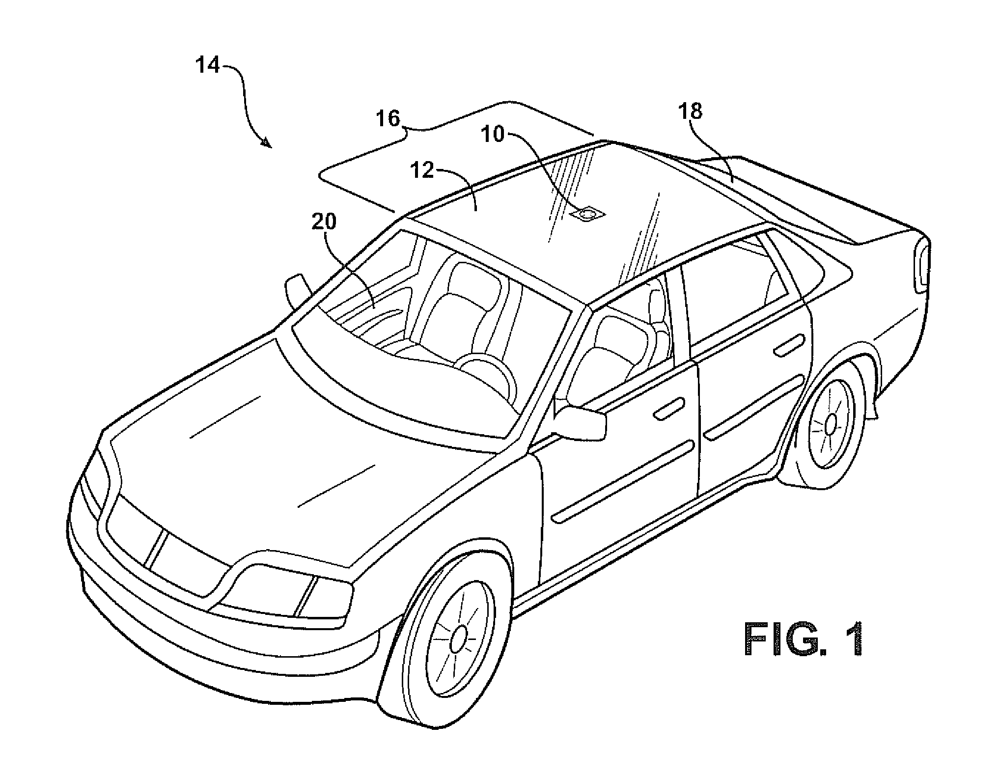
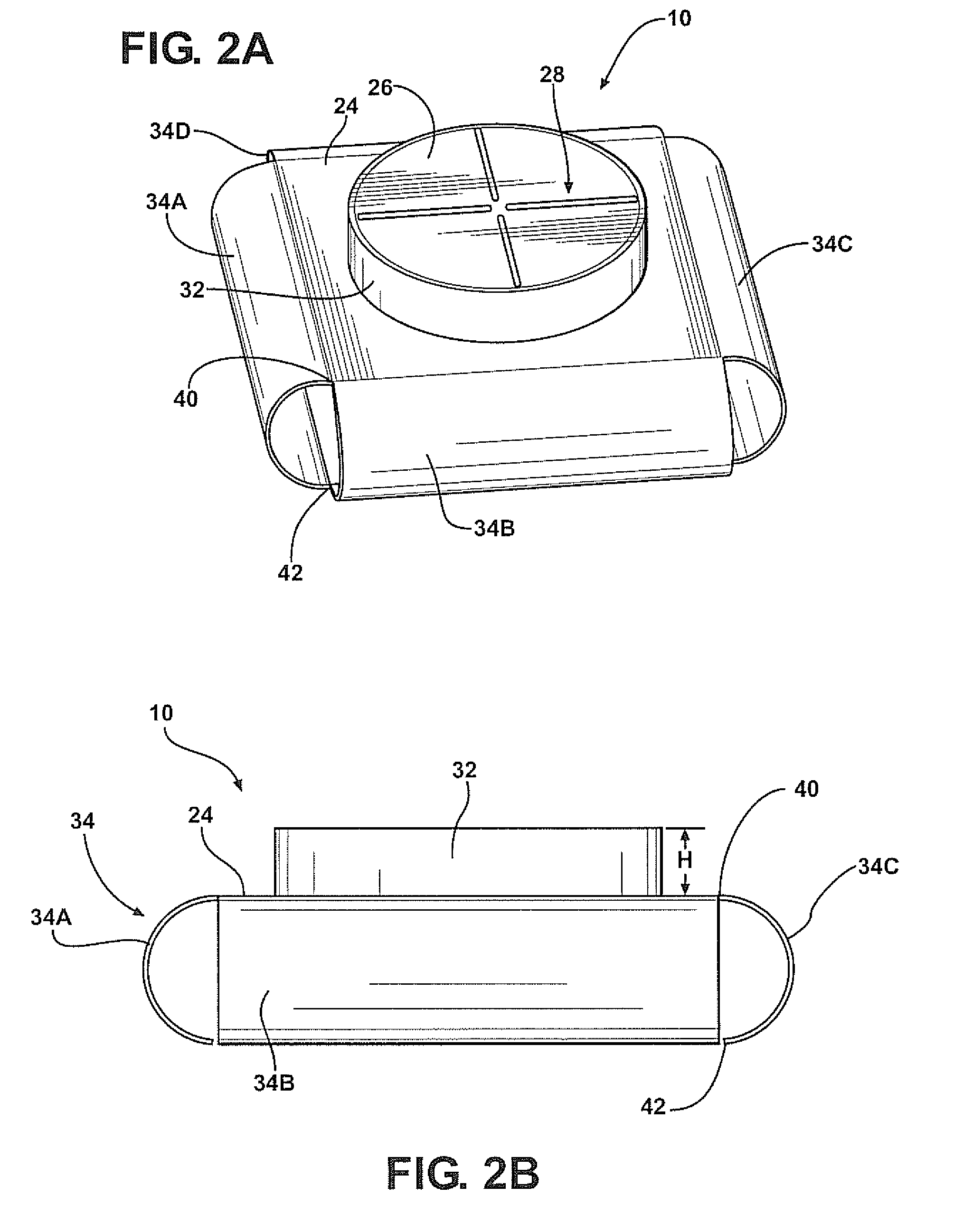
[0020]Referring to the Figures, wherein like numerals indicate like or corresponding parts throughout the several views, an antenna 10 is provided. As shown in FIG. 1, although not required, the antenna 10 is preferably integrated with a window 12 of a vehicle 14. The window 12 may be a roof window 16 (such as a glass roof), a rear window 18 (backlite), a front window 20 (windshield), or any other window of the vehicle 14 not integrated with the window 12. The antenna 10 of this invention may be located at other positions on the vehicle 14. The antenna 10 may also be implemented in other situations completely separate from the vehicle 14, such as on a building or integrated with a radio receiver.

[0021]The antenna 10 of this invention transmits and / or receives an RF signal. In a preferred embodiment, a particularly desired RF signal is a circularly polarized RF signal, and the antenna 10 is utilized for transmitting and / or receiving the circularly polarized RF signal from a satellite...


PUM


Abstract

An antenna includes a ground plane, a dielectric, and an active radiating element. The dielectric is disposed on the ground plane, and the active radiating element is embedded in the dielectric for transmitting and/or receiving an RF signal. The antenna also includes a feeding element and a passive radiating element. The feeding element extends into the dielectric and is electrically coupled to the active radiating element. The passive radiating element is disposed on the ground plane and surrounds a periphery of the dielectric for perturbating the RF signal. The ground plane has a plurality of edges. At least one of the edges extends as a curvilinear lip. The curvilinear lip extends in a direction opposite the passive radiating element for directing the RF signal and for preventing abrupt discontinuity of the RF signal.

Description

BACKGROUND OF THE INVENTION[0001]1. Field of the Invention[0002]The subject invention generally relates to an antenna which increases a beamwidth of an antenna radiation pattern. More specifically, the antenna of this invention achieves the increased beamwidth of the antenna radiation pattern with a ground plane having at least one edge which extends as a curvilinear lip, and with a passive radiating element.[0003]2. Description of Related Art[0004]Antennas for receiving radio frequency (RF) signals are known in the art. One example of such an antenna is disclosed in PCT Publication No. WO 02 / 069445 (the '445 publication). The '455 publication discloses an antenna array having a ground plane and a plurality of antenna elements on the ground plane. The ground plane includes a flat portion and a pair of rolled portions. The rolled portions extend from opposing ends of the flat portion of the ground plane to function as an “infinite” ground plane. The antenna array of the '455 publicat...

Claims


Application Information

Patent Timeline
Patent Type & Authority Applications(United States)
IPC IPC(8): H01Q1/38H01Q1/00H01Q21/26
CPCH01Q1/1271H01Q1/3275H01Q21/26H01Q9/285H01Q19/021H01Q1/48
Inventor LEE, KWAN-HOVILLARROEL, WLADIMIROHORIKI, YASUTAKALEE, MING
Owner AGC AUTOMOTIVE AMERICAS
Why Eureka
Try Eureka