
Conductive clamp and conductive transition device

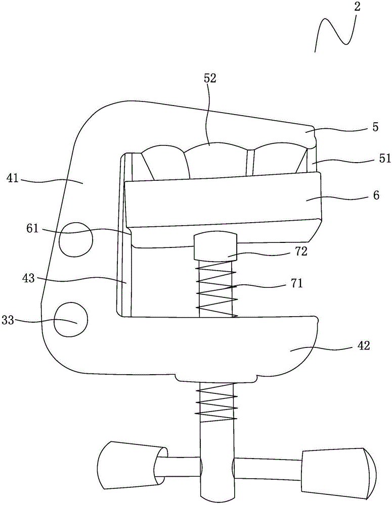
A technology of conductive clamps and fixed splints, applied in conductive connections, circuits, electrical components, etc., can solve the problems of increasing the time for maintenance personnel to install and remove conductive fixtures, affecting grounding, and endangering the safety of maintenance personnel, and reducing installation and disassembly. The time of the conductive fixture, avoiding the sudden interruption of grounding, and ensuring the effect of grounding reliability

Pending Publication Date: 2017-09-19
STATE GRID FUJIAN DEHUA POWER SUPPLY
View PDF9 Cites 0 Cited by
  • Summary
  • Abstract
  • Description
  • Claims
  • Application Information

AI Technical Summary

Problems solved by technology

However, the existing conductive transition device has the following defects: during use, the grounding body may fall off from the side of the conductive fixture, causing a sudden interruption of the grounding and endangering the safety of maintenance personnel; The low-voltage conductive fixture requires two sets of conductive fixtures to complete, which increases the time for maintenance personnel to install and remove the conductive fixture, and reduces work efficiency; the wire and the conductive fixture are connected by bolts, and the bolts are often loose during use, resulting in poor contact Phenomenon, affect the normal grounding, there is a safety hazard

Method used


Image

  • Conductive clamp and conductive transition device
  • Conductive clamp and conductive transition device

Examples


Embodiment Construction

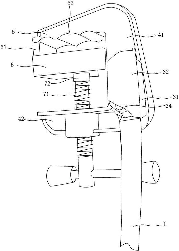
[0019] Such as figure 1 and figure 2 As shown, the conductive transition device includes a conductive wire 1, a conductive clamp 2 arranged at the end of the conductive wire 1, and a connection structure for connecting the conductive wire 1 and the conductive clamp 2. The conductive clamp 2 includes a base body and a fixed splint 5 fixedly arranged on the base body. 1. The movable splint 6 is arranged on the base so as to be movable relative to the fixed splint 5 through the locking mechanism. The front end of the fixed splint 5 is vertically provided with a blocking portion 51 extending toward one side of the movable splint 6. The blocking portion 51 is used to prevent the grounding body from falling off from the front end of the conductive fixture 2, so as to avoid sudden interruption of grounding; the side of the fixed splint 5 opposite to the movable splint 6 There are three grooves 52, which can clamp the grounding body of the high-voltage line and the grounding body of...


PUM


Abstract

The present invention provides a conductive clamp. The conductive clamp comprises a fixed clamping plate fixedly arranged on a base body and a movable clamping plate movably arranged on the base body relative to the fixed clamping plate through a locking mechanism, the front end of the fixed clamping plate is provided with a blocking portion extended towards one side of the fixed clamping plate. The present invention further provides a conductive transition device. The conductive clamp and the conductive transition device can prevent a grounding body from falling off from the front end of the conductive clamp to avoid sudden interruption of grounding, ensure the grounding reliability and eliminate hidden dangers.

Description

technical field [0001] The invention relates to a conductive clamp and a conductive transition device. Background technique [0002] When inspecting and maintaining the power supply line in the distribution station area, the conductive transition device (such as a conductive clamp) can be attached to prevent the damage to the human body caused by a sudden call, and it is a safety barrier to protect the maintenance personnel. The existing conductive transition device includes a wire and conductive clamps arranged at both ends of the wire, and the two conductive clamps are respectively used to clamp the grounding body of the power supply line and the grounding rod in contact with the earth. However, the existing conductive transition device has the following defects: during use, the grounding body may fall off from the side of the conductive fixture, causing a sudden interruption of the grounding and endangering the safety of maintenance personnel; The low-voltage conductive ...

Claims


Application Information

Patent Timeline
Patent Type & Authority Applications(China)
IPC IPC(8): H01R11/14H01R4/38
CPCH01R4/38H01R11/14
Inventor 林星魁黄成配许永全李丽雅林瑞苏林月阳王怡张节炜郭英英赖育斌林诗光
Owner STATE GRID FUJIAN DEHUA POWER SUPPLY
Learn More