Printed Antenna

a technology of printed antennas and antennas, applied in the field of printed antennas, can solve the problems of increasing material costs and raising defective fractions, and achieve the effect of widening the application field

Inactive Publication Date: 2011-06-30
ADVANCED CONNECTEK INC
View PDF3 Cites 8 Cited by
  • Summary
  • Abstract
  • Description
  • Claims
  • Application Information

AI Technical Summary

Benefits of technology

[0006]One objective of the present invention is to provide a printed antenna, which uses a conductive ink as the material of the radiation conductor, wherein the conductive ink is coated on a non-metallic plate, such as a glass plate, an acrylic plate or an LCD panel, to directly form a radiation conductor, whereby the present invention is exempt from the numerous complicated processes of fabricating the conventional metallic conductor, and whereby the present invention has a wider application field.

Problems solved by technology

Thus, a metallic radiation conductor usually has a complicated form, including angles, 3D deflections, curves, etc., which should need longer fabrication time, increase the material cost and raise the fraction defective.

Method used


Image

  • Printed Antenna
  • Printed Antenna
  • Printed Antenna

Examples


Embodiment Construction

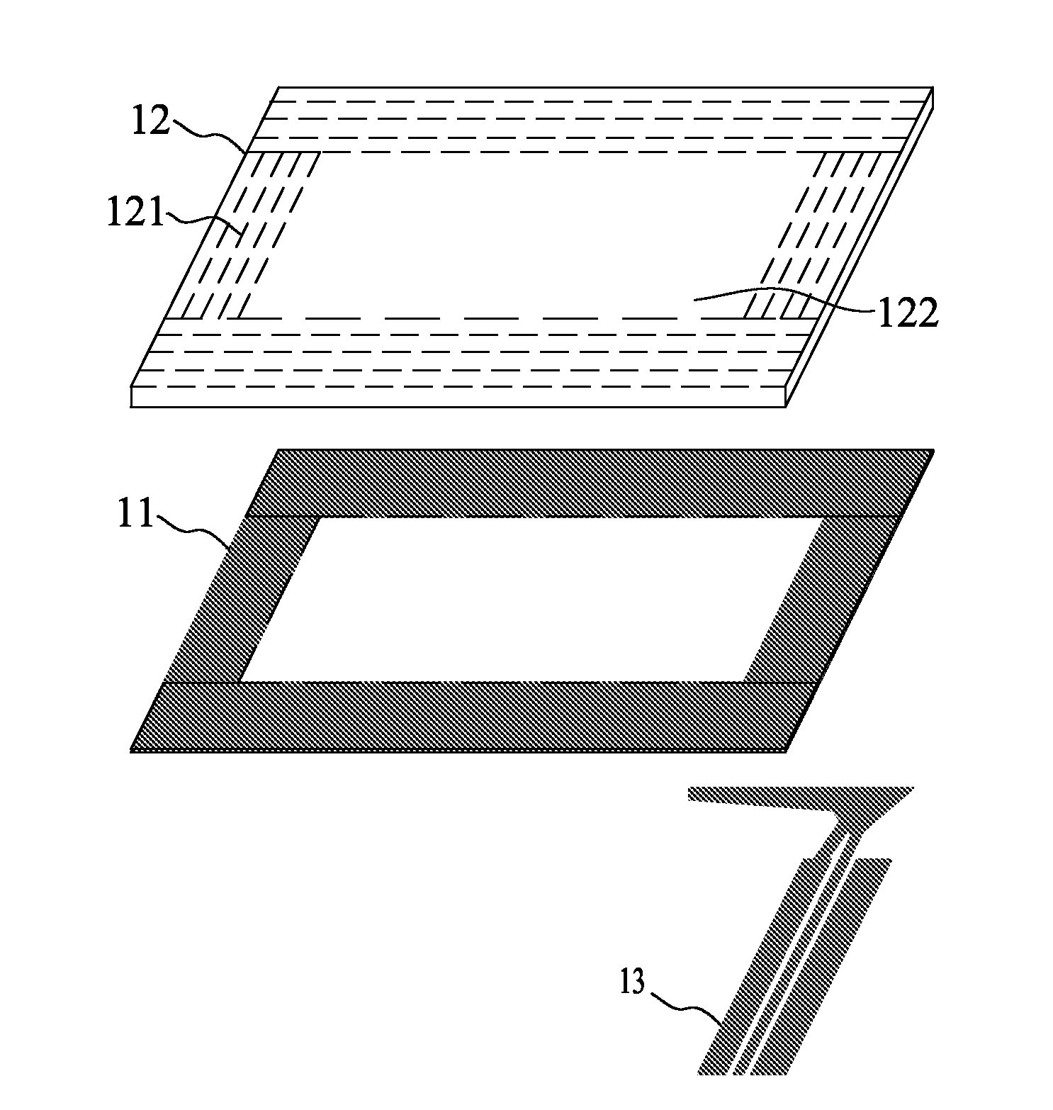
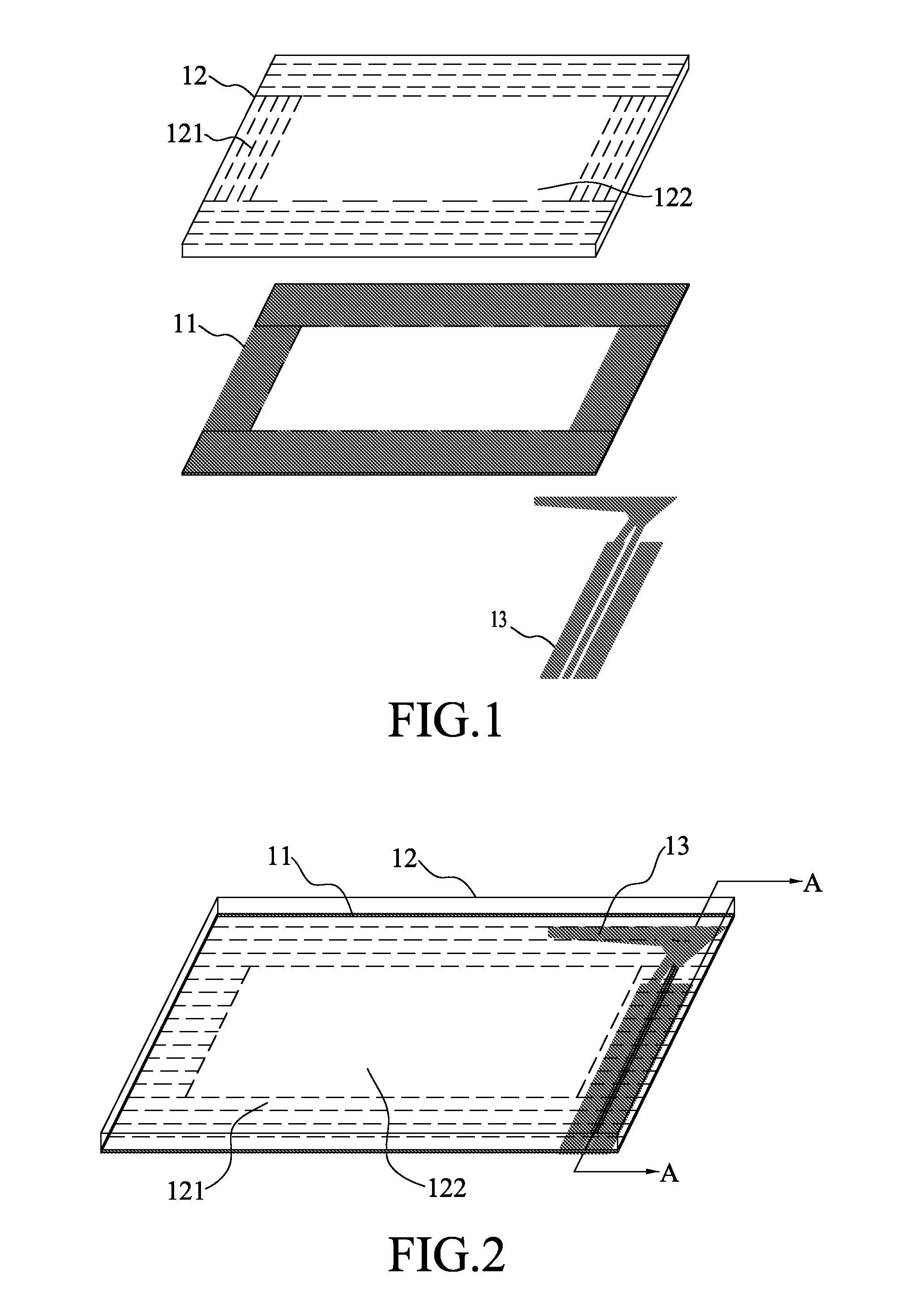
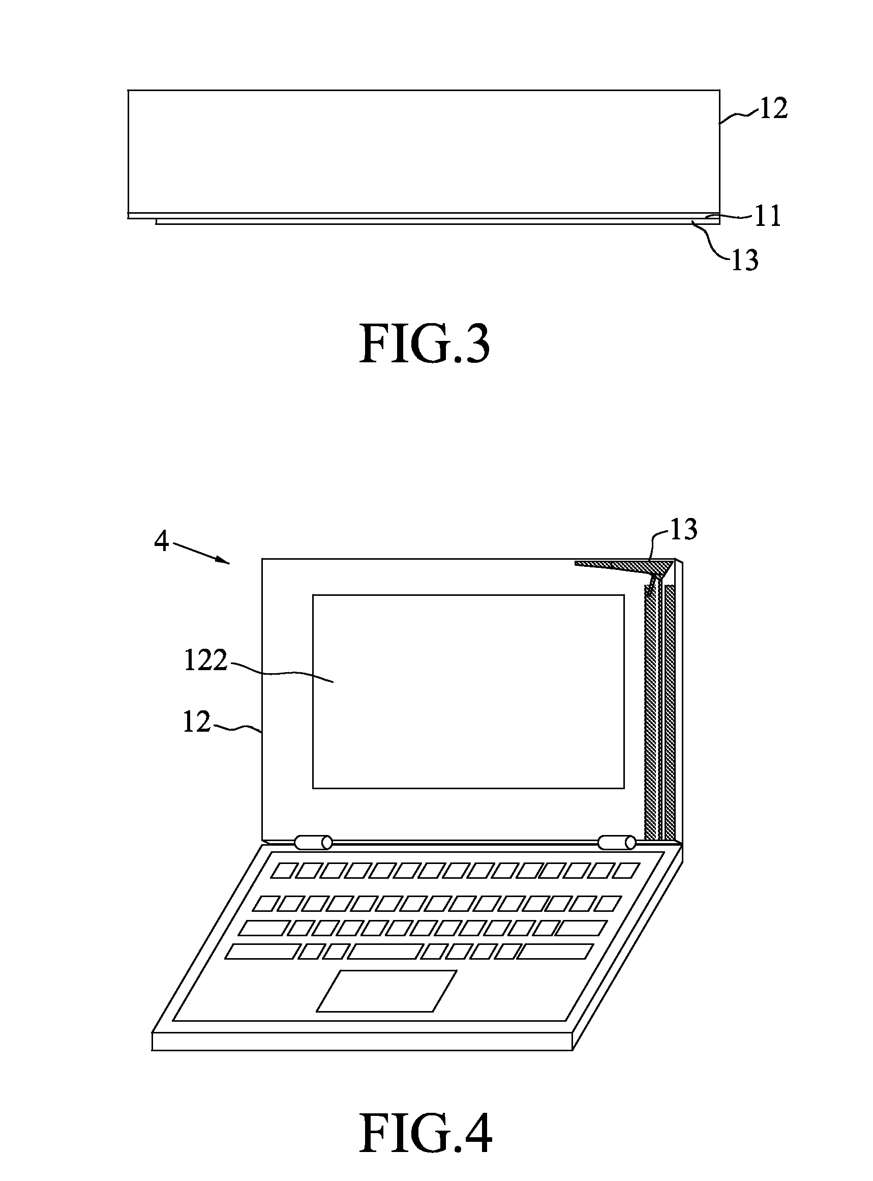
[0017]Refer to FIG. 1 and FIG. 2 respectively a perspective exploded view and a perspective assembly drawing schematically showing a printed antenna according to a first embodiment of the present invention. The printed antenna of the present invention comprises an ink-printed layer 11, a hard substrate 12 and a radiation conductor layer 13. The surface of the hard substrate 12 includes a non-transparent area 121 and a transparent area 122, and the non-transparent area 121 surrounds the transparent area 122.

[0018]In fabricating the printed antenna of the present invention, a high-viscosity black ink is uniformly coated on the non-transparent area 121 to form the ink-printed layer 11 encircling the hard substrate 12. The hard substrate 12 is a non-metallic transparent plate, such as a glass plate, an acrylic plate or an LCD panel. Thus, the transparent area 122 of the hard substrate 12 can function as the display screen of an electronic device. Next, a conductive ink is coated on the ...


PUM


Abstract

A printed antenna comprises an ink-printed layer, a hard substrate and a radiation conductor layer. The hard substrate has a surface, and the ink-printed layer is coated on the surface to form a non-transparent area. The uncoated region of the surface is a transparent area. The radiation conductor layer is formed on the ink-printed layer and does not exceed the non-transparent area of the hard substrate. In the present invention, a conductive ink is coated on the surface of a non-metallic plate, such as a glass plate, an acrylic plate or an LCD panel, to form the radiation conductor layer. Therefore, the printed antenna of the present invention is exempt from the complicated processes of fabricating the conventional metallic radiation conductors with the application field thereof expanded.

Description

BACKGROUND OF THE INVENTION[0001]1. Field of the Invention[0002]The present invention relates to a printed antenna, particularly to an antenna using a conductive ink as the material of the radiation conductor.[0003]2. Description of the Related Art[0004]With the progress of information science and technology, the portable computer has evolved from a simple business machine for word processing and financial computing to a multimedia device functioning as TV, a game machine, a CD / DVD player, and an IP phone. Many functions of the current portable computer depend on the internet access capability. With the popularization of wireless communication, the portable computer also becomes a multi-antenna environment, including the systems of Wi-Fi, WLAN, GSM and other wireless communication standards.[0005]The current portable computer usually adopts metals and a microwave medium circuit board as the materials of the antenna module. According to the desired operation frequency band, the resea...

Claims


Application Information

Patent Timeline
Patent Type & Authority Applications(United States)
IPC IPC(8): H01Q1/38H01Q1/00
CPCG06F1/1616G06F1/1698H01Q1/44H01Q1/38H01Q1/2266
Inventor CHIU, TSUNG-WENHSIAO, FU REN
Owner ADVANCED CONNECTEK INC
Why Eureka
Try Eureka