Method and apparatus for improving antenna radiation patterns
a radiation pattern and antenna technology, applied in the field of antenna apparatus, can solve the problems of more interference to the service region of other base stations, two signals of the same channel arriving at a mobile station from different base stations, and unwanted back lobe of the antenna radiation pattern of the sector antenna, so as to improve the antenna radiation pattern of the base station, the effect of improving the antenna radiation pattern
- Summary
- Abstract
- Description
- Claims
- Application Information
AI Technical Summary
Benefits of technology
Problems solved by technology
Method used
Image
Examples
first embodiment
The First Embodiment
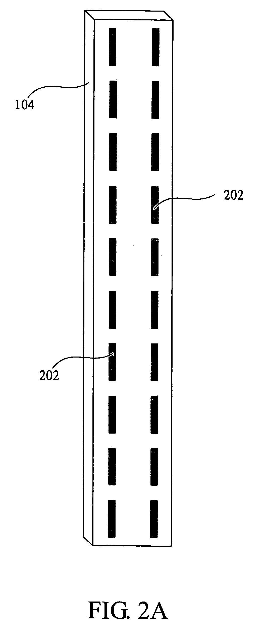
[0064]FIG. 2A illustrates a schematic view of the first embodiment of the present invention. In this embodiment, the electromagnetic scattering structure comprises a plurality of strip units 202. The length of the strip unit 202 is half of the corresponding wavelength at the central working frequency, which is about 76 mm, and the width of the strip unit 202, which is not critical, is 2 mm in this embodiment. The strip units 202 are arranged periodically in two rows and in front of the antenna inside the radome 104 (i.e. the array antenna 102 as illustrated in FIG. 1). The two rows are configured on the surface of the radome 104, and each is spaced a quarter wavelengths from each closer edge of the radome 104.
[0065]FIG. 2B illustrates far-field antenna radiation patterns in the horizontal plane of the first embodiment, and the radial axis thereof represents the relative field value in dB. The curve 222 is the antenna radiation pattern without the electromagnetic...
second embodiment
The Second Embodiment
[0067]FIG. 3A illustrates a schematic view of the second embodiment of the present invention. In this embodiment, the electromagnetic scattering structure comprises two strip units 302. The length of the strip unit 302 is the same as the length of the radome 104, and the width of the strip unit 302, which is not critical, is 2 mm in this embodiment. The two strip units 302 are in front of the antenna inside the radome 104 (i.e. the array antenna 102 as illustrated in FIG. 1), and are configured on the surface of the radome 104
[0068]FIG. 3B illustrates far-field antenna radiation patterns in the horizontal plane of the second embodiment, and the radial axis thereof represents the relative field value in dB. The curve 322 is the antenna radiation pattern without the electromagnetic scattering structure of the embodiment, and the curve 324 is the antenna radiation pattern of the antenna with the electromagnetic scattering structure. FIG. 3C illustrates far-field an...
third embodiment
The Third Embodiment
[0070]FIG. 4A illustrates a schematic view of the third embodiment of the present invention. In this embodiment, the electromagnetic scattering structure comprises a plurality of cross units 402. Each of the cross units 402 has two strip portions 412a and 412b with identical lengths. The length of the strip portions 412a and 412b is a half the corresponding wavelength at the central working frequency, and the widths of the strip portions 412a and 412b, which are not critical, are both 2 mm in this embodiment. The cross units 402 are in front of the antenna inside the radome 104 (i.e. the array antenna 102 as illustrated in FIG. 1), and are configured in two rows interleaving on the surface of the radome 104.
[0071]FIG. 4B illustrates far-field antenna radiation patterns in the horizontal plane of the third embodiment, and the radial axis thereof represents the relative field value in dB. The curve 422 is the antenna radiation pattern without the electromagnetic s...
PUM
 Abstract
Description
Claims
Application Information
 - R&D
- Intellectual Property
- Life Sciences
- Materials
- Tech Scout
- Unparalleled Data Quality
- Higher Quality Content
- 60% Fewer Hallucinations
Browse by: Latest US Patents, China's latest patents, Technical Efficacy Thesaurus, Application Domain, Technology Topic, Popular Technical Reports.
© 2025 PatSnap. All rights reserved.Legal|Privacy policy|Modern Slavery Act Transparency Statement|Sitemap|About US| Contact US: help@patsnap.com


