Compact portable auger rack for single-operator function

a portable, auger rack technology, applied in the direction of drilling rods, drilling pipes, cabinets, etc., can solve the problems of cumbersome transportation from one location, difficult to transport a plurality of augers simultaneously, and the weight of the auger itself can be hundreds of pounds or mor

Inactive Publication Date: 2012-09-20
HOKANSON CRAIG RICHARD
View PDF9 Cites 11 Cited by
  • Summary
  • Abstract
  • Description
  • Claims
  • Application Information

AI Technical Summary

Benefits of technology

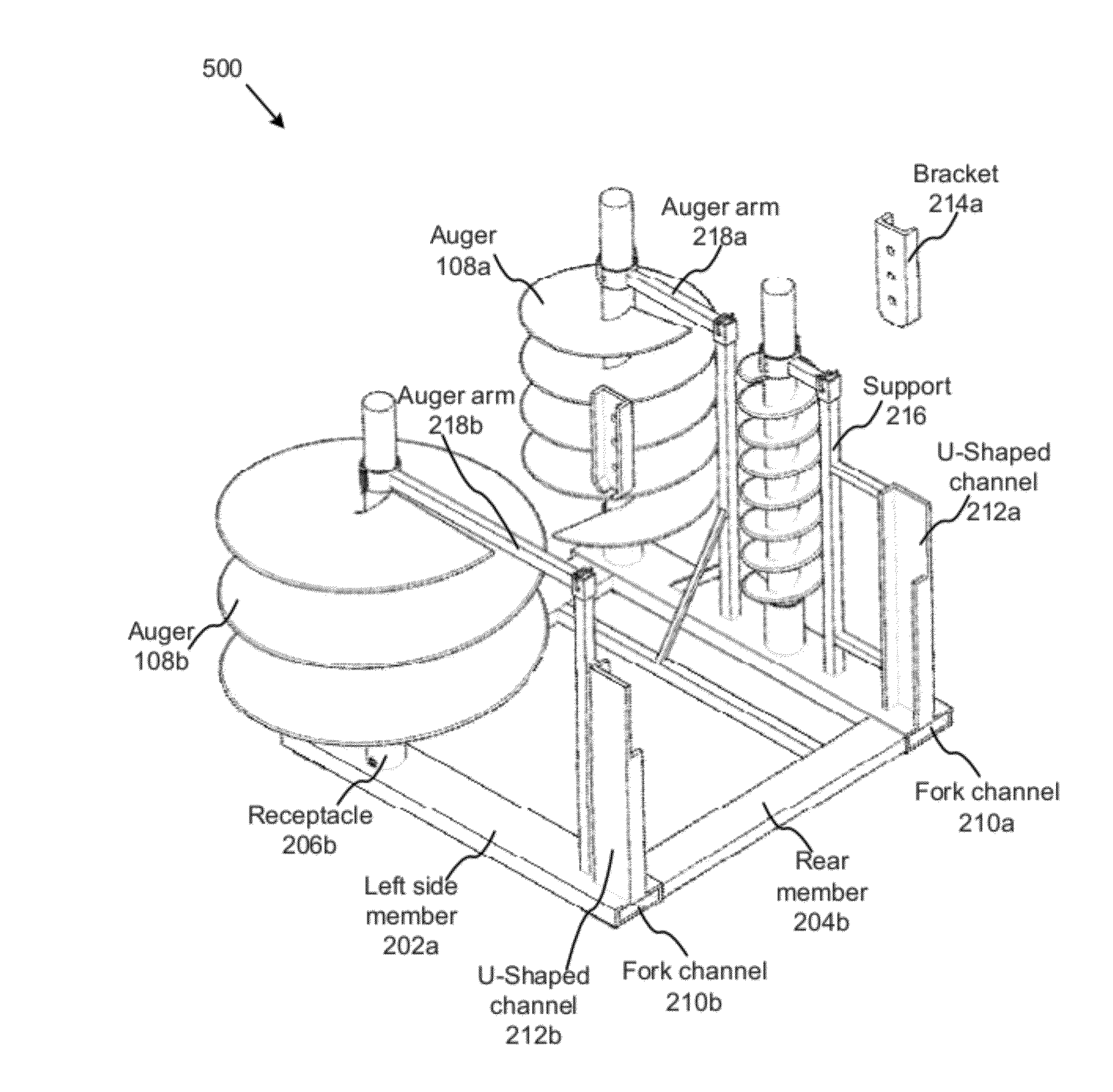
[0027]FIG. 5 is an elevational perspective view an auger rack,

Problems solved by technology

The augers themselves can weigh hundreds of pounds or more, and are cumbersome to transport from one location to another.
Because of their size, it is difficult to transport a plurality of augers simultaneously, and there exists no efficient means in th

Method used


Image

  • Compact portable auger rack for single-operator function
  • Compact portable auger rack for single-operator function
  • Compact portable auger rack for single-operator function

Examples


Embodiment Construction

[0028]Reference throughout this specification to “one embodiment,”“an embodiment,” or similar language means that a particular feature, structure, or characteristic described in connection with the embodiment is included in at least one embodiment of the present invention. Thus, appearances of the phrases “in one embodiment,”“in an embodiment,” and similar language throughout this specification may, but do not necessarily, all refer to the same embodiment.

[0029]Furthermore, the described features, structures, or characteristics of the invention may be combined in any suitable manner in one or more embodiments. In the following description, numerous specific details are provided to provide a thorough understanding of embodiments of the invention. One skilled in the relevant art will recognize, however, that the invention may be practiced without one or more of the specific details, or with other methods, components, materials, and so forth. In other instances, well-known structures, ...


PUM


Abstract

A portable auger rack is disclosed, adapted to allow a single operator to transport a plurality of augers and an auger drive unit, as well as to allow a single operator to connect the drive unit and augers unassisted to a skid-steer, Bobcat®, or other variation of track equipment.

Description

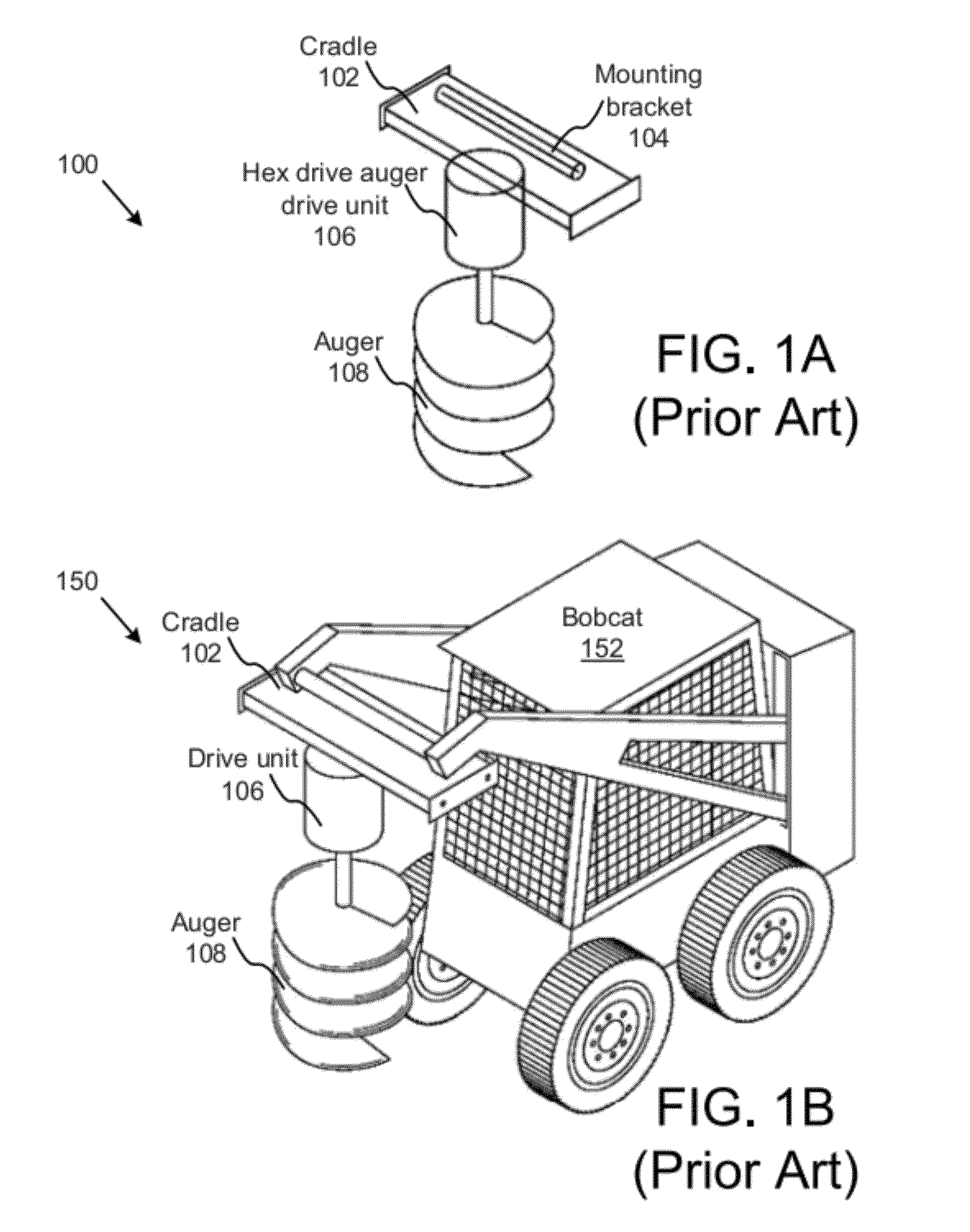
BACKGROUND OF THE INVENTION[0001]1. Field of the Invention[0002]This invention relates to construction equipment, and more particularly relates to transporting and storing augers used in drilling earth in connection with construction.[0003]2. Description of the Related Art[0004]Augers and auger drive units are well-known in the art. Earth augers comprise sharp helical tools used in drilling to extract earth and aggregate from a construction area. Augers are also used to facilitate the construction of wells, the installation of piping, and the like. Augers are used in a various apparatii to move fluids, gravel, grain, snow, oil, and the like, from one position to another.[0005]In construction, standard augers, which are used to drill holes in earth, can range from just a few inches in diameter to more than four feet in diameter. These augers often comprise sharp bits detachably connected to the forward end of the auger for engaging rock and other aggregates. The augers themselves can...

Claims


Application Information

Patent Timeline
IPC IPC(8): E21B19/14A47B81/00E21B7/00A47F7/00
CPCE21B19/14
Inventor HOKANSON, CRAIG RICHARD
Owner HOKANSON CRAIG RICHARD
Why Eureka
Try Eureka