Pull-out blocking device

a technology of pulling device and pull-out, which is applied in the direction of mechanical control, furniture parts, domestic applications, etc., to achieve the effect of improving the pull-out blocking devi

Active Publication Date: 2012-09-27
FULTERER GES
View PDF3 Cites 10 Cited by
  • Summary
  • Abstract
  • Description
  • Claims
  • Application Information

AI Technical Summary

Benefits of technology

[0005]It is the object of the invention to improve pull-out blocking devices of the generic type with regard to a structure which is as simple as possible.
[0007]It is thus a basic concept of the invention to use, instead of the previous multipart construction, support elements which have, as an inherently rigid body, at least both the upper supporting surface and the lower supporting surface and also the further supporting surface. These three supporting surfaces are thus formed in an inherently rigid manner in the form of a body, this body, that is to say the respective support element, being mounted on the guide element such as to be pivotable about a pivot axis between the blocking position and the releasing position. With regard to the design of the support elements as a single, inherently rigid body, the support elements can also be known in a corresponding manner as blocking hooks or blocking bodies. These inherently rigid bodies according to the invention which form the support elements can of course also have more than just supporting surfaces. The fact that all of the supporting surfaces are arranged outside the guide element makes it possible, by way of a correspondingly large design of the supporting surfaces and correspondingly large distances between the supporting surfaces, to make available a relatively large travel between the blocking position and the releasing position.
[0014]It is also favorable for the displaceability of the support elements along the guide element to be confined between two stops, all the remaining or other support elements being fixed in position in relation to the stops when or after at least one of the support elements has been arranged in its blocking position. This is applicable in particular when all the other pull-out furniture parts, or drawers, are already intended to be blocked when a single pull-out furniture part, or a single drawer, is extracted from the basic furniture structure. If the intention is to allow more than one pull-out furniture part to be pulled out of the basic furniture structure, then the remaining support elements are fixed between the stops only when a corresponding number of support elements are arranged in their blocking position. This can be set up easily by corresponding arrangements of the stops in coordination with the dimensioning of the support elements.

Problems solved by technology

Usually, such pull-out blocking devices already block the pulling-out of further pull-out furniture parts when just a single pull-out furniture part has been pulled out of the basic furniture structure.

Method used


Image

  • Pull-out blocking device
  • Pull-out blocking device
  • Pull-out blocking device

Examples


Embodiment Construction

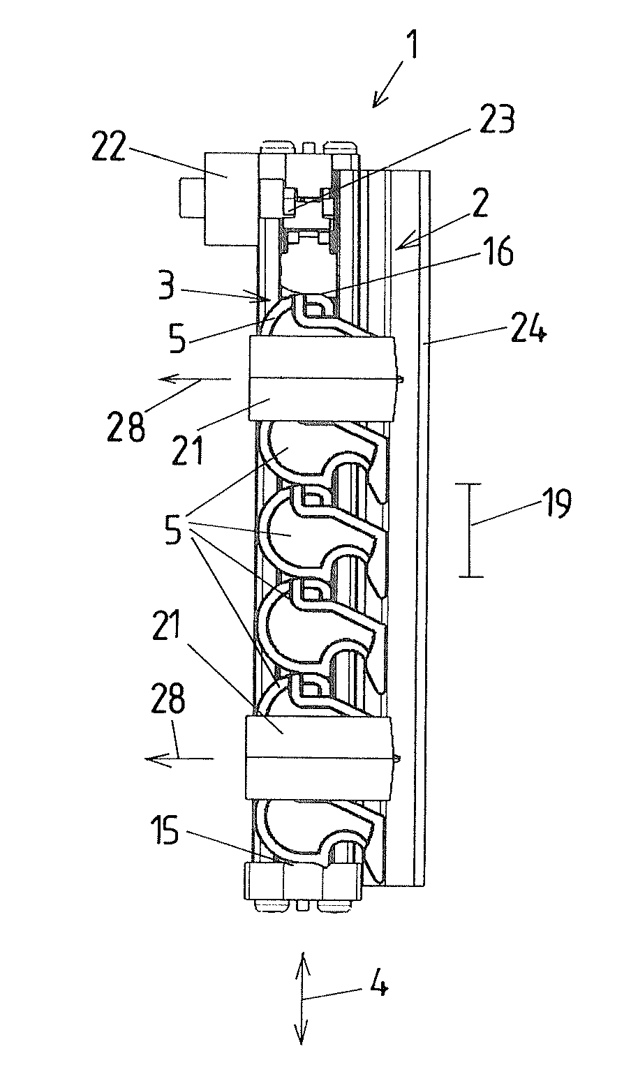
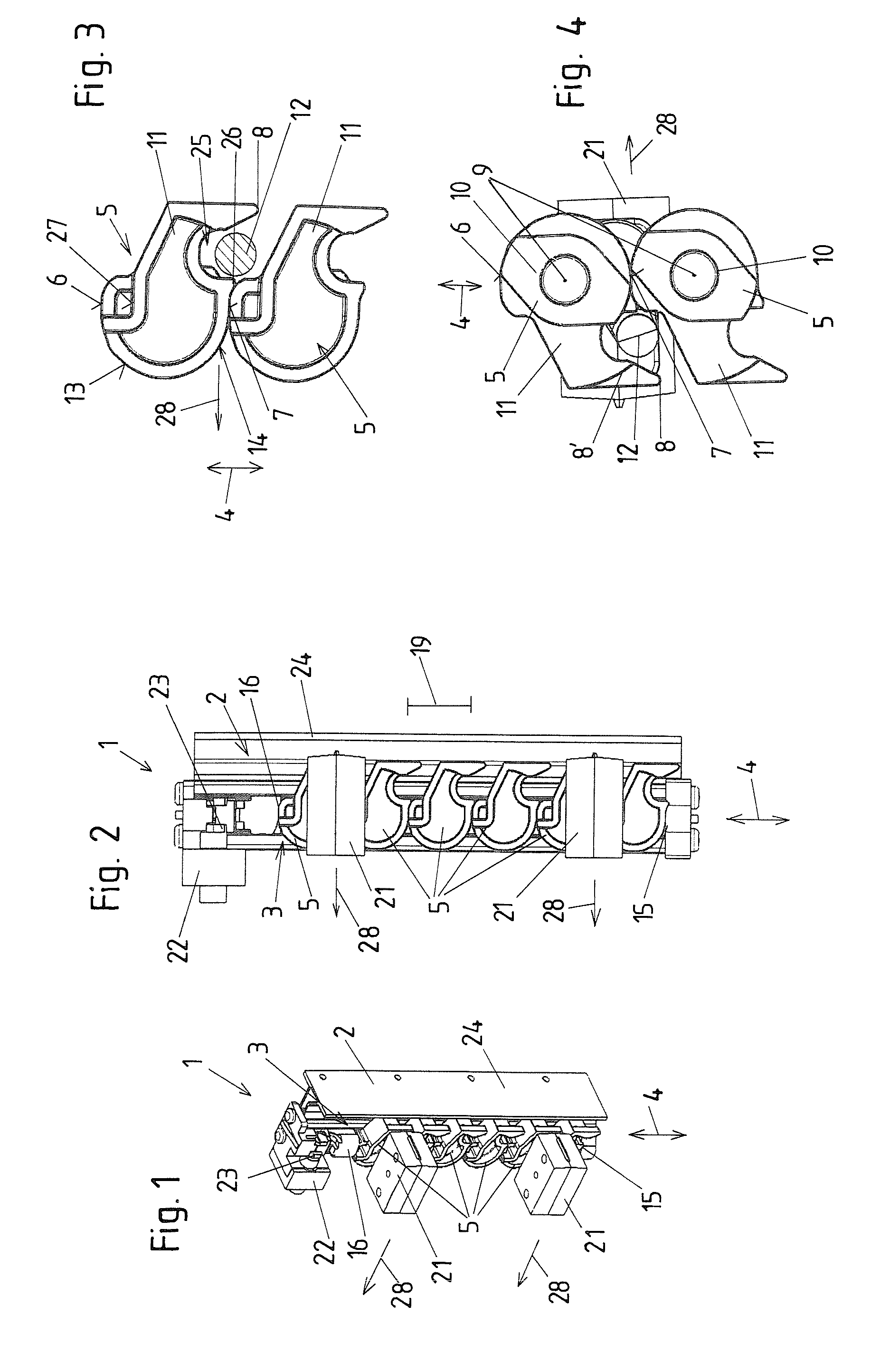
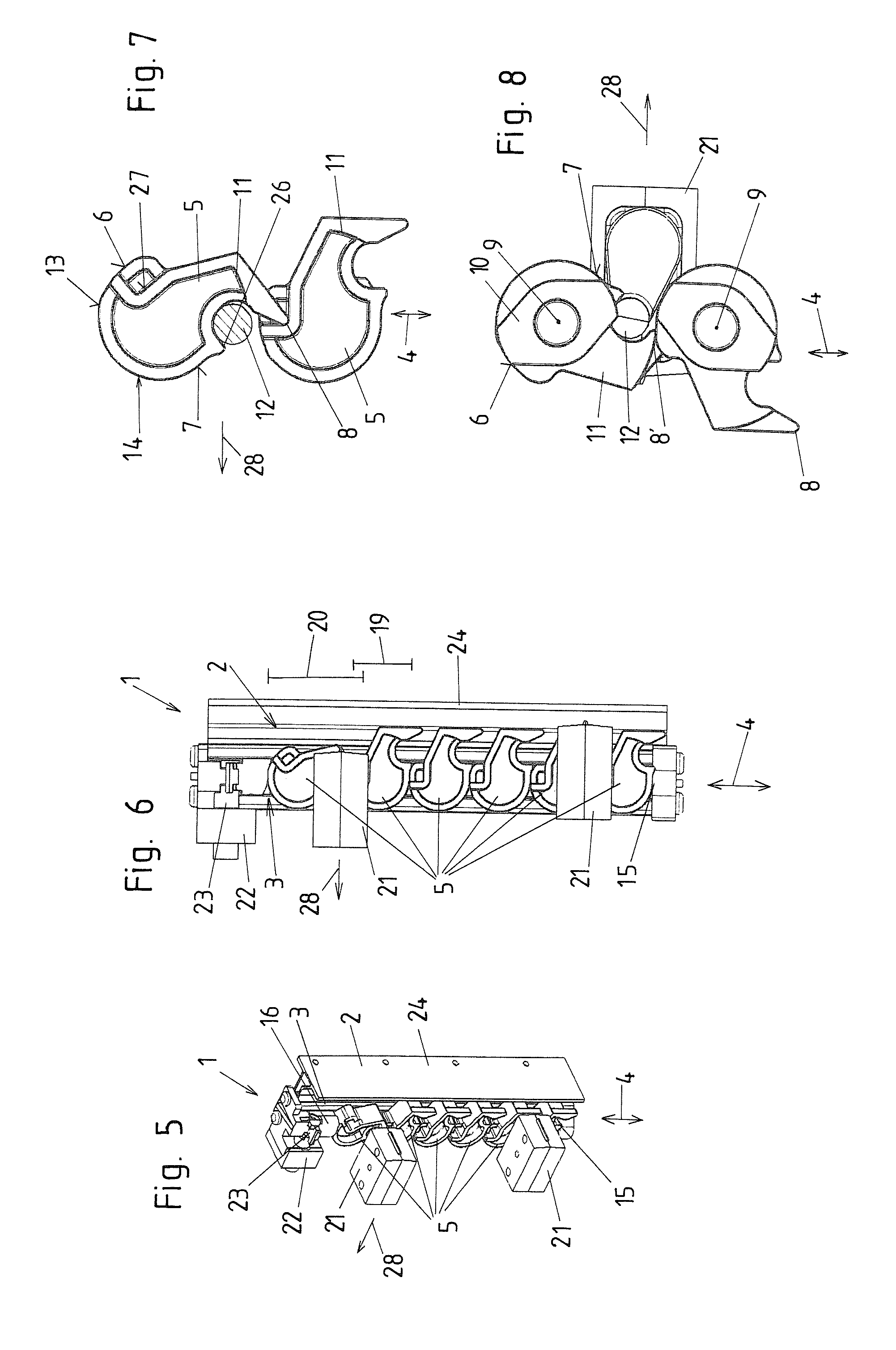
[0021]Four different operating states are shown for the first exemplary embodiment in FIGS. 1 to 16. In each case four figures are present for each operating state. FIGS. 1 to 4 show an operating state in which the pull-out furniture parts, or drawers, which are not shown here, have been pushed completely into the basic furniture structure, which is likewise not shown. Thus, all the support elements 5 are still in their releasing position, in which one of the furniture parts which are not illustrated here can be pulled out of the basic furniture structure. FIGS. 5 to 8 and FIGS. 9 to 12 show two operating states that occur directly after one another, when, while one of the movable furniture parts, in this case the upper one, is being pulled out of the basic furniture structure, one of the support elements 5 has already been pivoted into its blocking position. FIGS. 13 to 16 then show the situation in which the trigger element 12 has been pulled completely out of the arrangement of s...


PUM


Abstract

A pull-out blocking device for furniture parts that can be pushed into or pulled out of a basic furniture structure, the pull-out blocking device having at least one guide rail and a sequence of support elements mounted on the guide rail displaceable in the longitudinal direction thereof, each support element having an upper supporting surface for abutment against a support element arranged adjacently above, a lower supporting surface for abutment against a support element arranged adjacently below and at least one further supporting surface for abutment against the support element arranged adjacently above or below. Each support element is formed as a body that connects the upper, lower, and further supporting surfaces together in an inherently rigid manner, and each support element is pivotably arranged on the guide element for movement between the blocking and releasing positions, and all the supporting surfaces are arranged outside the guide element.

Description

BACKGROUND[0001]The present invention relates to a pull-out blocking device for at least two furniture parts that can be pushed into a basic furniture structure and can be pulled out of the basic furniture structure, in particular drawers, the pull-out blocking device having at least one guide rail and a sequence of support elements mounted on an elongate guide element of the guide rail such as to be displaceable in the longitudinal direction thereof, each support element having, as seen in an operating position of the pull-out blocking device, an upper supporting surface for abutment against a support element arranged adjacently above and a lower supporting surface for abutment against a support element arranged adjacently below and at least one further supporting surface for abutment against the support element arranged adjacently above or below, each support element having a releasing position for abutment by way of its upper supporting surface against the support element arrange...

Claims


Application Information

Patent Timeline
Patent Type & Authority Applications(United States)
IPC IPC(8): E05B65/46E05B65/464
CPCE05B65/464E05B65/46A47B88/04A47B88/477A47B88/40
Inventor FULTERER, AXEL
Owner FULTERER GES
Why Eureka
Try Eureka