Manipulation holder for cryomicroscopy

a technology for manipulation containers and cryomicroscopy, which is applied in the field of manipulation containers for cryomicroscopy, can solve problems such as relatively complex systems, and achieve the effect of effectively driving moisture from the environmen

Active Publication Date: 2016-02-04
LEICA MICROSYSTEMS GMBH +1
View PDF1 Cites 7 Cited by
  • Summary
  • Abstract
  • Description
  • Claims
  • Application Information

AI Technical Summary

Benefits of technology

[0008]The object on which the invention is based is therefore that of refining a manipulation container of the kind recited previously in such a way that standardized and convenient manipulation of sample carriers and sample carrier mounts, and in particular the conveyance of sample carriers in sample carrier mounts as described above, is possible under cold and anhydrous conditions, and displacement of the sample carrier mounts having the sample carriers out of the same manipulation container into, for example, a cryo-light microscope can be accomplished without involving the relatively high physical complexity of a vacuum cryotransfer system.
[0010]The functionality such that the holder is movable into the displacement path of a displacement apparatus can be implemented in any manner. According to a preferred embodiment of the present invention, however, provision is made that the holder for a sample carrier mount is displaceable along a track crossing the displacement path of the displacement apparatus. If, as in the case of this preferred embodiment of the present invention, the holder for a sample carrier mount is displaceable along a track, the holder is always fixedly guided; this allows the user to move the holder, without particular manual skill and especially with the use of simple tools such as metal pins and the like, out of a manipulation position in the container into the displacement path of the displacement apparatus. The track can have any conceivable profile, although it is self-evident to one skilled in the art that the profile of the track has a shape corresponding to the shape of the holder for a sample carrier mount, in order to guide the holder securely and ensure good displaceability of the holder in the track.
[0011]In order to further simplify the handling of the samples or sample carriers and sample carrier mounts in the manipulation container according to the present invention, provision is made according to a preferred embodiment of the present invention that along the track at least one rest position for the holder for a sample carrier mount in the displacement path of the displacement apparatus is defined; and at least one further rest position for the holder for a sample carrier mount is defined, in which position the holder abuts in planar fashion against a support for a sample carrier mount so that a sample carrier mount can be displaced from the support onto the holder for a sample carrier mount. According to this preferred variant, at least two preferred rest positions for the holder are therefore furnished, in which positions in the one case the holder occupies a defined site in which the holder is positioned in the displacement path of the displacement direction [sic] in order to grasp the sample carrier mount after manipulation and subsequently displace it, and in the other case the holder abuts in planar fashion against a support for a sample carrier mount, i.e. the holder abuts seamlessly against the support in order to permit simple displacement of the sample carrier mount from the support on which the sample carrier or sample carrier mount are manipulated onto the holder for the sample carrier mount.
[0013]The holder for a sample carrier mount which is utilized in the context of the manipulation container according to the present invention serves to retain the sample carrier mount for insertion of the sample carrier, and after insertion of the sample carrier to move the sample carrier mount, together with the sample carrier, into the displacement path of the displacement apparatus and retain it there. For this purpose, provision is preferably made that the holder for a sample carrier mount comprises at least two mutually independent clip elements for frictionally engaged holding of the sample carrier mount. Thanks to the provision of clip elements, a sample carrier mount can easily be slid onto the holder beneath the clip elements, and no further elements need to be actuated in order to sufficiently secure the sample carrier mount on the holder.
[0017]It is particularly preferred in this context if the second tube comprises attachment means for attaching the tube to a microscope stage. A sufficiently sealed closure between the manipulation container and a microscope stage can be produced in this manner, so that penetration of moist air to the sample in the context of manipulation and transfer of the sample carriers or the sample carrier mounts can be effectively prevented.
[0019]According to a preferred embodiment, in order to further ensure an anhydrous atmosphere in the manipulation container, the manipulation container is covered by a transparent cover that is held by spacing pins on the manipulation container. A cover spaced away from the manipulation container in this manner limits the quantity of liquid nitrogen, or of cold nitrogen gas formed therefrom, that is needed in order to effectively drive moisture from the environment out of the interior of the manipulation container, while at the same time at least slight manipulation capabilities are provided by the gap between the cover and the manipulation container. The cover can of course be entirely removed for more complex manipulations.

Problems solved by technology

This system is relatively complex, however, since it is a vacuum system that offers only a limited manipulation clearance and entails relatively complex handling of the corresponding samples in the manipulation container.

Method used


Image

  • Manipulation holder for cryomicroscopy
  • Manipulation holder for cryomicroscopy
  • Manipulation holder for cryomicroscopy

Examples


Embodiment Construction

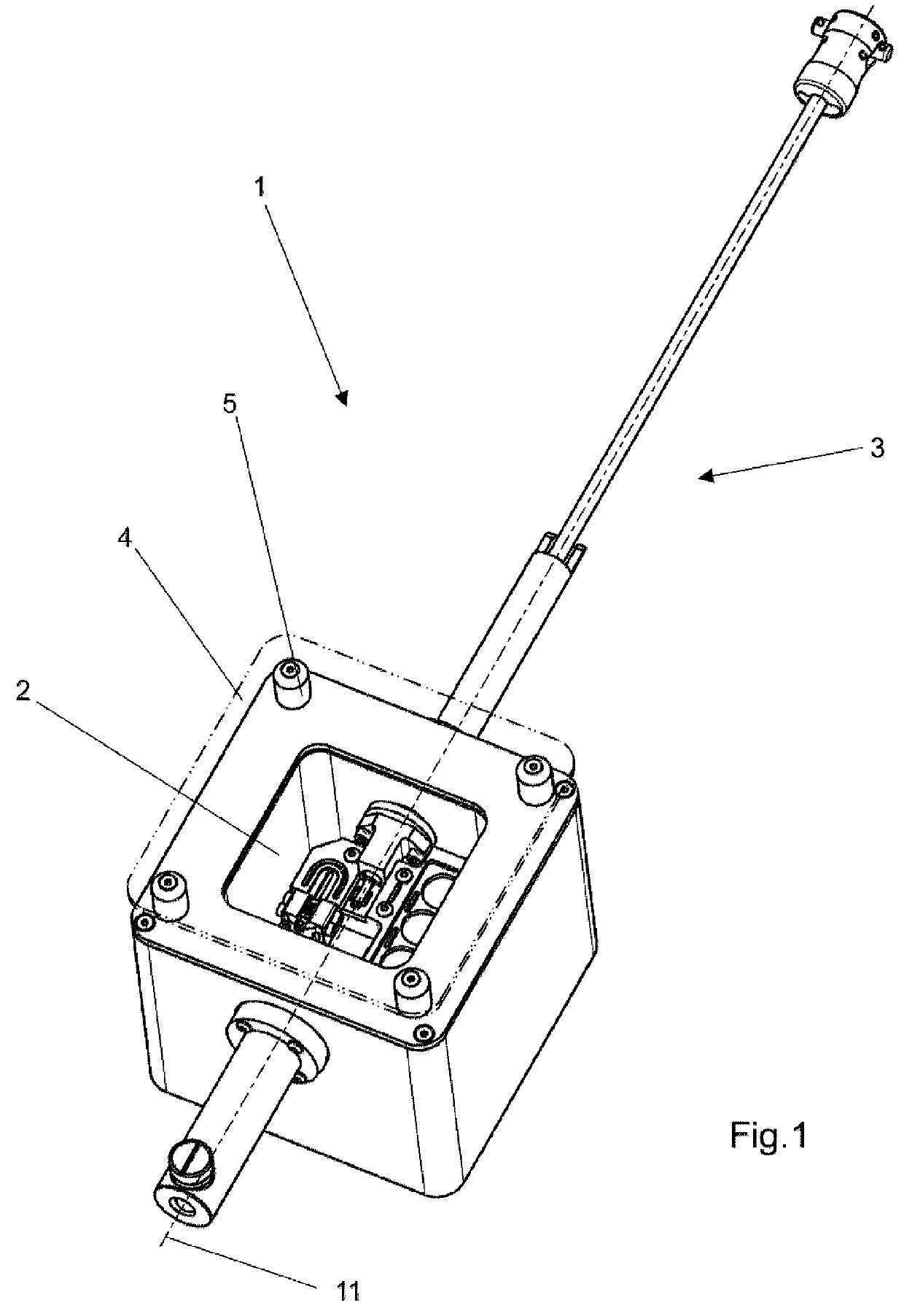
[0026]In FIG. 1, a manipulation container according to the present invention is labeled 1. The manipulation container comprises a manipulation opening 2 for the manipulation of sample carriers or sample carrier mounts, and furthermore possesses a displacement apparatus 3 whose displacement path 11 passes completely through manipulation container 1. The number 4 designates a transparent cover that is held on the manipulation container with the aid of spacing pins 5.

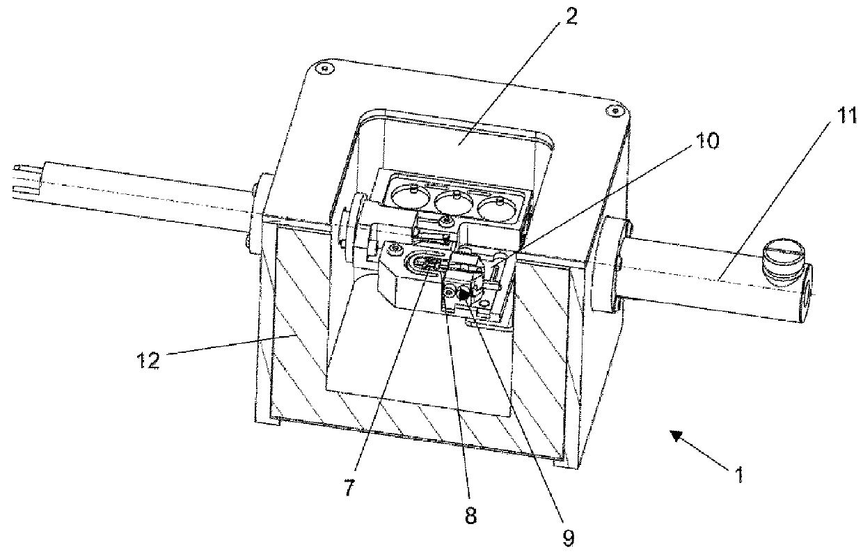
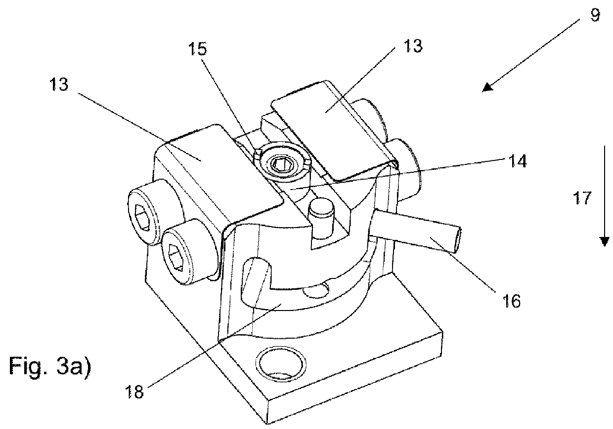
[0027]It is apparent from the larger depiction in FIG. 2 that manipulation container 1, for which cover 4 is not depicted in this view, possesses in its manipulation opening 2 or in the corresponding manipulation space 6 a number of internal fittings that enable or simplify the manipulation of samples or of sample carrier mounts. It is evident that a sample carrier mount 7 can be placed on a corresponding support 8 against which a holder 9 for a sample carrier mount 7 abuts in planar fashion, so that a sample carrier mount...


PUM


Abstract

In a manipulation container (1) for cryomicroscopy, having at least one holder (9) for a sample carrier mount (7) and at least one manipulation opening (2) for manipulating sample carriers or sample carrier mounts (7), the holder (9) for a sample carrier mount (7) is movable into a displacement path (11), passing completely through the manipulation container (1), of a displacement apparatus (3) for the sample carrier mount (7).

Description

CROSS-REFERENCE TO RELATED APPLICATIONS[0001]This application claims priority of German patent application number 10 2014 110 724.1 filed Jul. 29, 2014, the entire disclosure of which is incorporated by reference herein.FIELD OF THE INVENTION[0002]The invention relates to a manipulation container for cryomicroscopy, having at least one holder for a sample carrier mount and at least one manipulation opening for manipulating sample carriers or sample carrier mounts.BACKGROUND OF THE INVENTION[0003]Cryofixation is a sample preparation method frequently used in electron microscopy. In it, a water-containing sample is frozen very quickly (cryofixed) to a temperature of less than −150° C., i.e. it is cooled very rapidly in order to avoid the formation of ice crystals. Cryofixation has proven to be particularly suitable for investigations of structural biology. The objects to be investigated, for example cells, enzymes, viruses, or lipid layers, thereby become embedded in a thin, vitrified...

Claims


Application Information

Patent Timeline
Patent Type & Authority Applications(United States)
IPC IPC(8): B01L9/00
CPCB01L9/00B01L2200/087B01L2300/041B01L2200/025B01L2300/0609G02B21/34B01L7/50B01L9/50B01L2200/185
Inventor LIHL, REINHARDGAECHTER, LEANDERBRIGGS, JOHNSCHORB, MARTIN
Owner LEICA MICROSYSTEMS GMBH
Why Eureka
Try Eureka