
Touch panel and touch display panel

Inactive Publication Date: 2012-10-11
WINTEK CORP +1
View PDF3 Cites 15 Cited by
  • Summary
  • Abstract
  • Description
  • Claims
  • Application Information

AI Technical Summary

Benefits of technology

[0007]The invention is directed to a touch panel and a touch display panel. Here, a non-black color layer serves as a border of the touch panel and can achieve satisfactory light shielding effects.
[0010]Based on the above, the non-black color layer and the reflective pattern layer are configured in the peripheral area of the touch panel, and the non-black color layer is located between the reflective pattern layer and the cover plate. At this time, the reflective pattern layer is conducive to shielding light. Thus, it is not necessary to increase the thickness of the non-black color layer in order to sufficiently shield light. Namely, the non-black color layer located in the peripheral area of the touch panel allows the touch panel to have a non-black border and can still achieve satisfactory light shielding effects. Even though the non-black color layer that is configured in the touch panel, the transmission lines of the touch panel can be formed with ease and do not encounter the problem of disconnection.

Problems solved by technology

From the perspective of a user, the black border does not necessarily meet the user's requirement for the exterior of the apparatus.
Hence, when the non-black ink material or the photoresist material is applied to form the border, the excessively large thickness of the material complicates the fabrication of the transmission lines.
The transmission lines may even encounter the problem of disconnection.

Method used


Image

  • Touch panel and touch display panel
  • Touch panel and touch display panel
  • Touch panel and touch display panel

Examples


Embodiment Construction

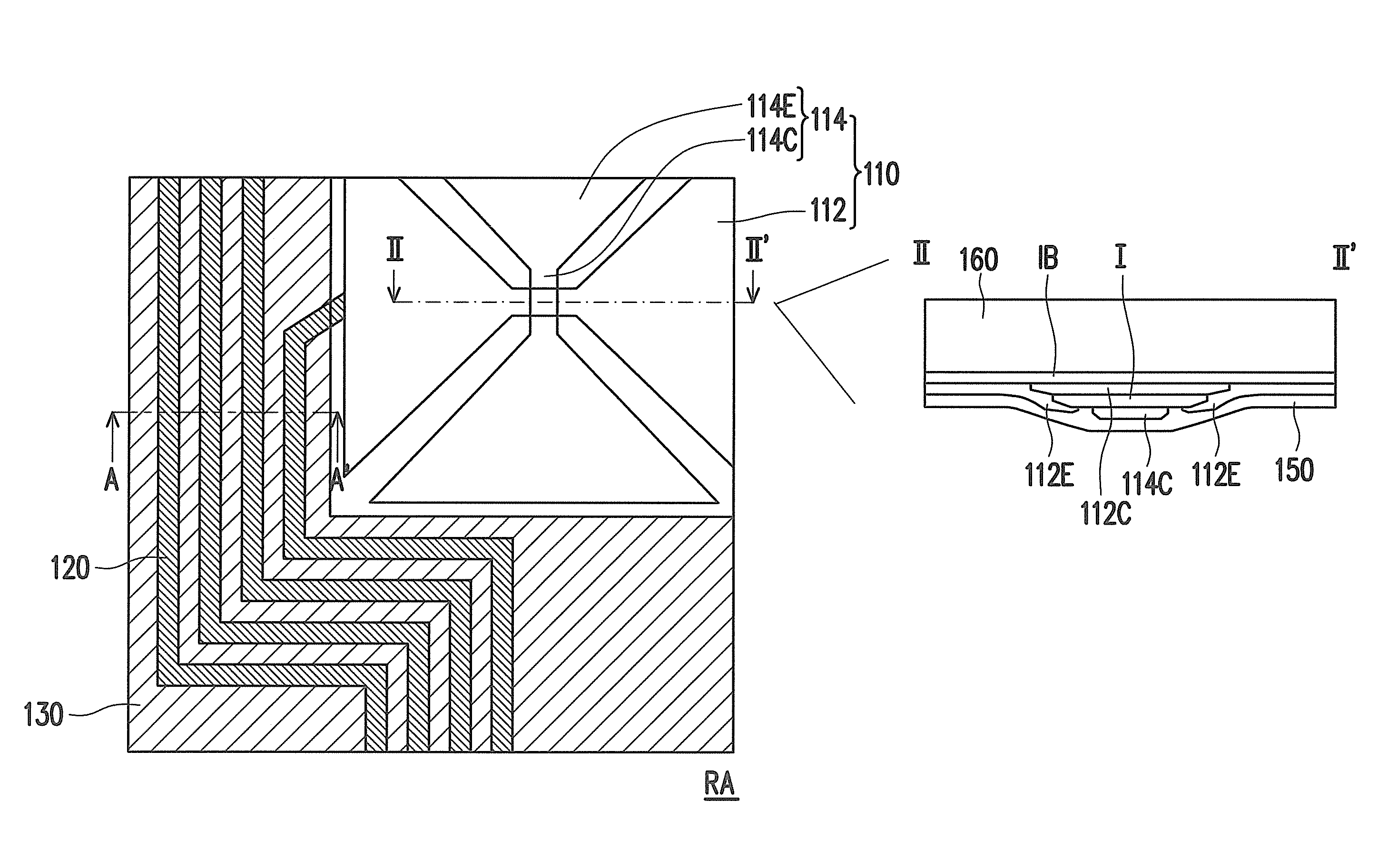
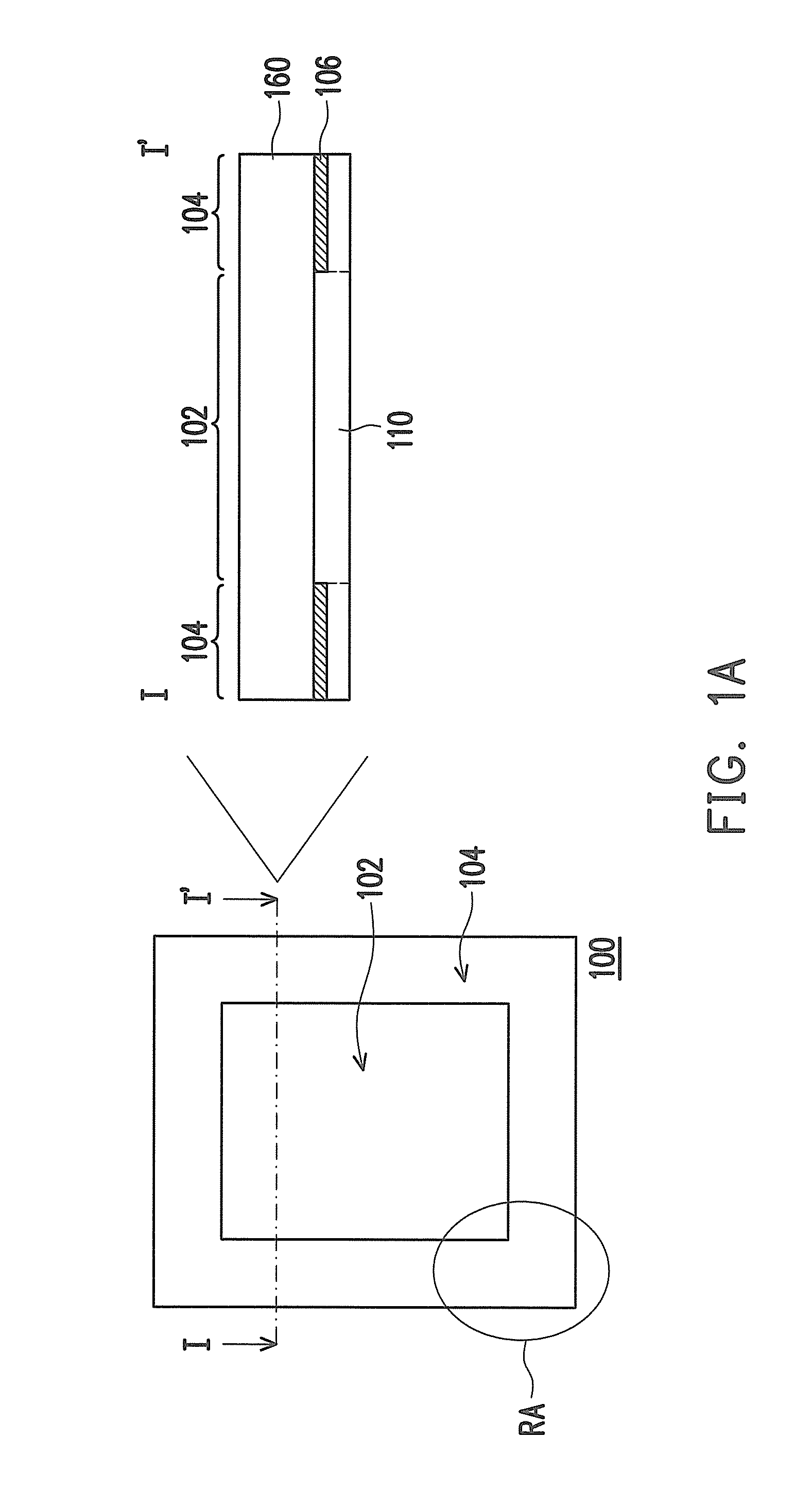
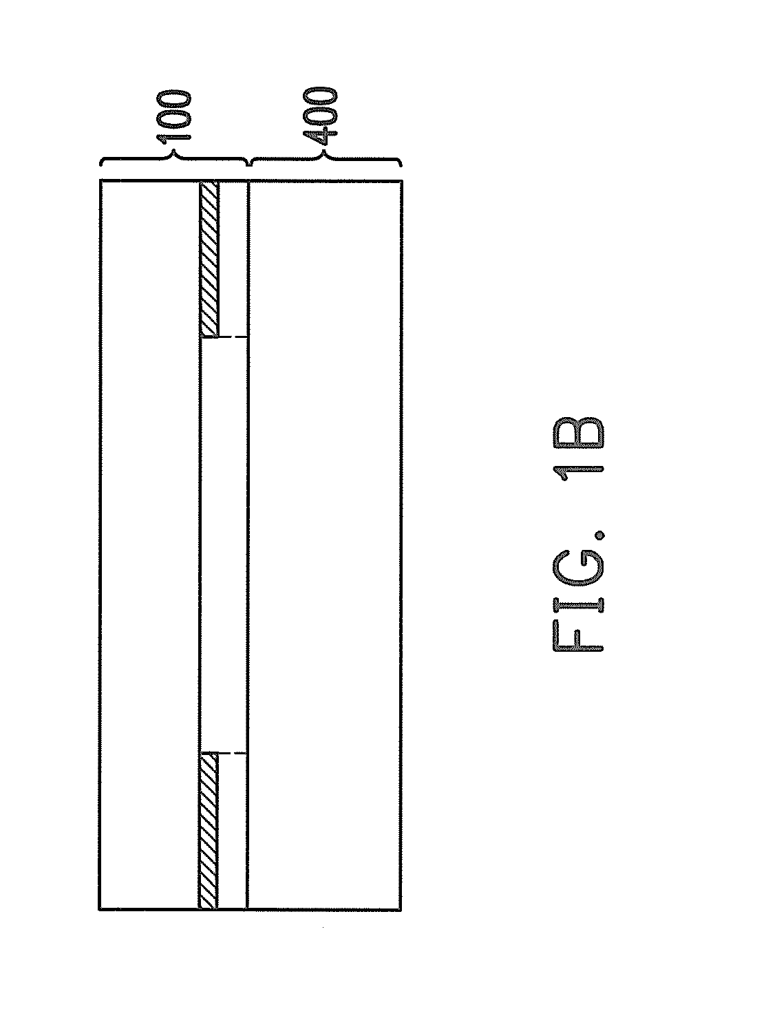
[0024]With reference to FIG. 1A, FIG. 1B, and FIG. 2, the touch panel 100 has an active area 102 and a peripheral area 104 surrounding the active area 102. In general, after the touch panel 100 is assembled to a display panel 400 to form a touch display panel, a user is allowed to operate the touch display panel through the active area 102 and view images through the active area 102 due to the transparency property of the active area 102. Here, the display panel 400 is a liquid crystal display (LCD) panel, an organic light emitting display panel, an electrowetting display panel, an electrophoretic display, or any other flat panel display (FPD).

[0025]To achieve the touch sensing function, the touch panel 100 includes a touch sensing element 110 that is configured on the cover plate 160, and the touch sensing element 110 is configured in the active area 102. Peripheral element 106 that are constituted by transmission lines 120 and other elements can be configured on the peripheral are...


PUM


Abstract

A touch panel has an active area and a peripheral area surrounding the active area. The touch panel includes a cover plate, a touch sensing element, a non-black color layer, transmission lines, a reflective pattern layer, and a protection layer. The touch sensing element is on the cover plate and in the active area. The non-black color layer is on the cover plate and in the peripheral area. The transmission lines at a side of the non-black color layer away from the cover plate and in the peripheral area electrically connect the touch sensing element. The reflective pattern layer is configured at the side of the non-black color layer away from the cover plate and at least located in a partial region of the peripheral area not covered by the transmission lines. The protection layer is configured at a side of the transmission lines away from the cover plate.

Description

CROSS-REFERENCE TO RELATED APPLICATION[0001]This application claims the priority benefit of Taiwan application serial no. 100112224, filed Apr. 8, 2011. The entirety of the above-mentioned patent application is hereby incorporated by reference herein and made a part of this specification.BACKGROUND OF THE INVENTION[0002]1. Field of the Invention[0003]The invention relates to a touch panel and a touch display panel. More particularly, the invention relates to a touch panel in which a border is not black and a touch display panel having the touch panel in which a border is not black.[0004]2. Description of Related Art[0005]A touch display apparatus includes a display panel and a touch panel configured on the display panel. A plurality of transmission lines are configured in a peripheral area of the touch panel in order to transmit signals. In the touch display apparatus, a black ink layer is often configured at a location corresponding to the peripheral area, so as to cover the transm...

Claims


Application Information

Patent Timeline
IPC IPC(8): G06F3/041H03K17/975
CPCG06F3/041H03K2217/96046H03K2217/96042H03K17/96G06F3/04164G06F3/0446
Inventor WANG, PO-HSIENCHEN, HSUAN-YANG
Owner WINTEK CORP
Learn More