Scintillator member and manufacturing method thereof, and radiation measuring device

a technology of scintillator and manufacturing method, applied in the field of scintillator parts, can solve the problems of reducing the measuring sensitivity, affecting the measurement accuracy, so as to achieve the effect of reducing manufacturing costs, enhancing physical strength, and transferring thin film onto the scintillator simply and reliably

Active Publication Date: 2006-07-13
NIPPON RAYTECH CO LTD
View PDF4 Cites 15 Cited by
  • Summary
  • Abstract
  • Description
  • Claims
  • Application Information

AI Technical Summary

Benefits of technology

[0022] (3) In accordance with still another aspect, the present invention provides a method of manufacturing a scintillator member using a transfer sheet including a base layer and a film, comprising at least one transfer step of transferring the film from the transfer sheet onto a scintillator plate, wherein the transfer step includes a step of applying heat or pressure onto the transfer sheet while the transfer sheet is being superimposed on the scintillator plate to thereby separate the film from the transfer sheet and adhere the film onto the scintillator plate, and wherein the film includes a light tight layer which transmits radiation therethrough and also prevents transmission of light.
[0023] With the above structure, it is possible to form a film having a light tight layer on a scintillator plate by using a simple method of transfer, thereby allowing reduction in manufacturing cost. Further, prior to the transfer, the film is integrated with a base layer and is therefore placed in a stout state, and after the thermal transfer, the film is integrated with the scintillator plate and is therefore placed in a stout state. Here, it is al

Problems solved by technology

In particular, as the range of P rays in the air is small, a light tight film having a certain degree of thickness which is formed on the front surface side of a scintillator member would make blockage and attenuation of radiation on that surface non-negligible, thereby considerably lowering the measuring sensitivity.
Such a thin light tight film, however, has a very low physical strength and is also easy to corrode, when used on its own.
Further, when the light tight film is scratched or has pinholes formed by scratching, light enters through such pinholes, making it impossible to detect weak light emission generated in the scintillator member.
Here, while a protective grille having a lattice shape may be provided on the front surface side of the outermost light tight film as required, there is a possibility that foreign matter or a contaminant may enter through any of the openings of the lattice.
This task requires technical skill and takes an immense amount of time and labor.
Further, the light tight film will easily tear when an excessive force is applied thereto during the disposing operation.
Conventionally, these problems are very significant because, in general, a plurality of light tight films are mounted on a radiation measuring instrument.
However, the light tight layer is rem

Method used


Image

  • Scintillator member and manufacturing method thereof, and radiation measuring device
  • Scintillator member and manufacturing method thereof, and radiation measuring device
  • Scintillator member and manufacturing method thereof, and radiation measuring device

Examples


Embodiment Construction

[0032] Preferred embodiments of the present invention will be described in detail with reference to the accompanying drawings.

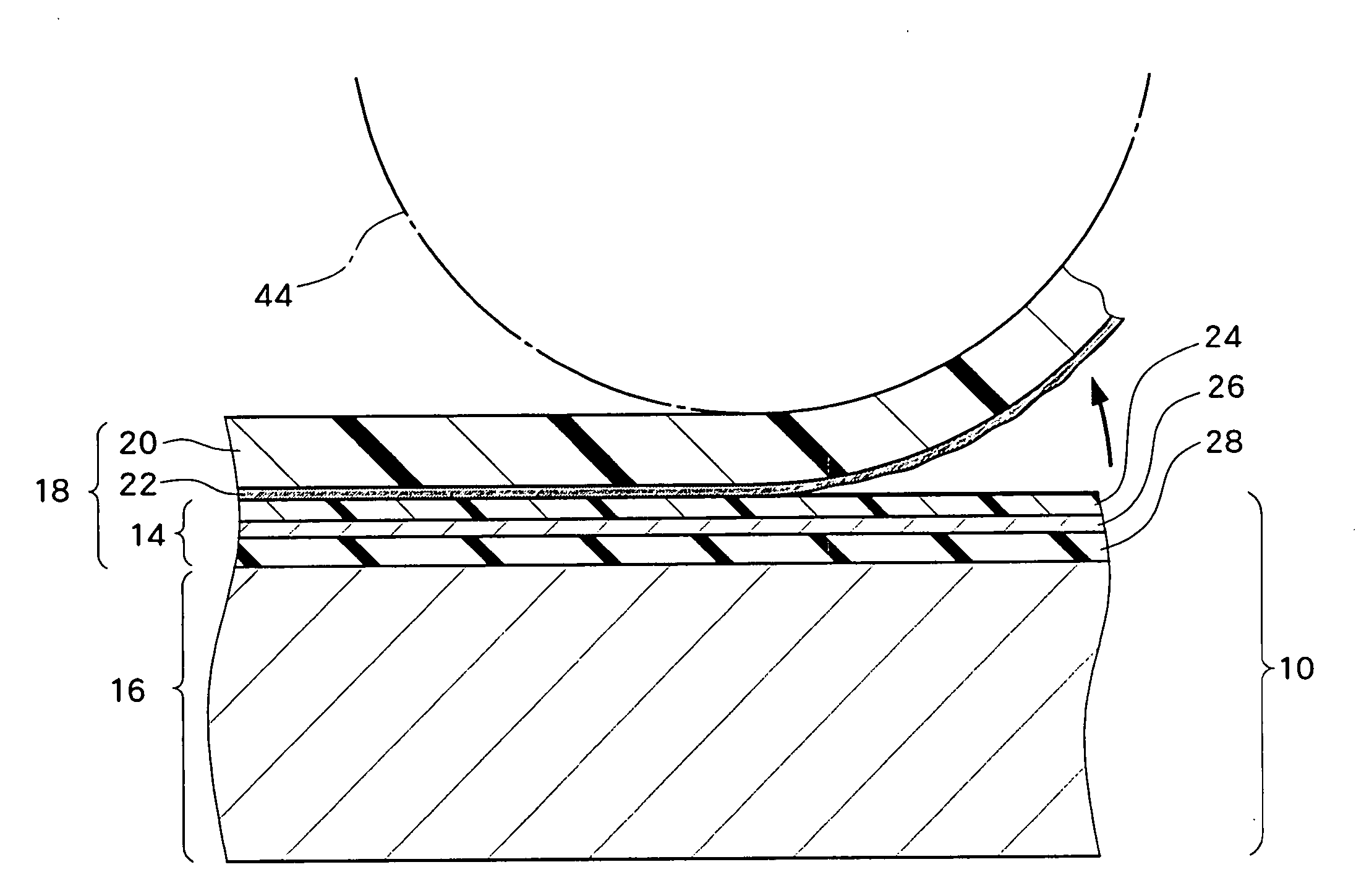
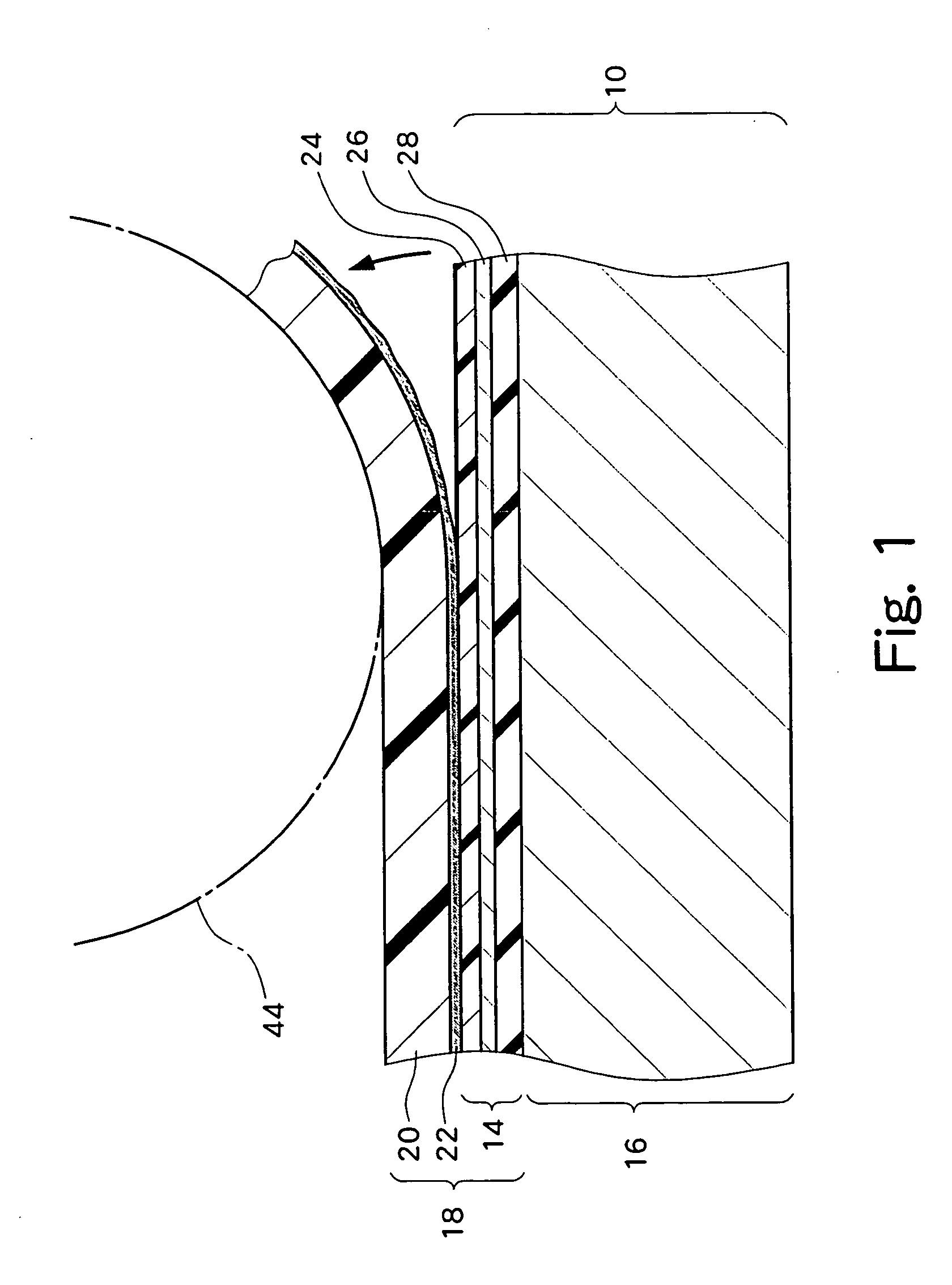
[0033]FIG. 1 shows a manufacturing method of a scintillator member (scintillator assembly or scintillator construction) 10 according to an embodiment of the present invention. The scintillator member 10 is used as a radiation detector in a radiation measuring device. The scintillator member 10 is composed of a scintillator plate 16 and a thin film 14.

[0034] While a scintillator member including one film which is formed on a surface. (a radiation entering surface) of the scintillator plate 16 is shown in FIG. 1, a plurality of films 14 may be layered on the surface of the scintillator plate 16.

[0035] The scintillator plate 16 is formed of a plastic scintillator material. As is known, the scintillator plate 16, when hit by radiation, emits light, and the emitted light is then detected on a rear surface side of the scintillator plate 16. The radiation may inc...


PUM


Abstract

When a heating process is performed in a state where a thermal transfer sheet is superimposed on a scintillator plate, a film of the thermal transfer sheet is separated from the thermal transfer sheet and adhered onto the scintillator plate. The film includes a protective layer, an aluminum layer, and an adhesive layer. The aluminum layer is protected by the protective layer. Because the scintillator plate by itself functions as a rear surface support substrate with respect to the protective layer and the aluminum layer, a film which is highly resistive against an external effect can be formed. A plurality of films can be layered on the scintillator plate. A pressure transfer method can also be used for formation of the film. A scintillator member in which the film has been formed is disposed in a radiation measuring device.

Description

BACKGROUND OF THE INVENTION [0001] 1. Field of the Invention [0002] The present invention relates to a scintillator member (scintillator assembly or scintillator construction) and to a manufacturing method thereof, and a radiation measuring device, and more particularly to light shielding technology of a scintillator member. [0003] 2. Description of Related Art [0004] Scintillator members are used in various radiation measuring instruments including a surface contamination measuring instrument, a body surface monitor, and so on. When excited by radiation, a scintillator member emits light, which is then directed onto a light receiving surface of a photomultiplier tube (PMT). In order to detect the light generated in the scintillator with high sensitivity, a light shielding structure or a light tight structure (a dark room) for shielding the scintillator member from external light is provided on both rear and front surface sides of the scintillator member. [0005] With regard to light...

Claims


Application Information

Patent Timeline
IPC IPC(8): G01T1/20
CPCG01T1/2002
Inventor MINAGAWA, EIICHIMATSUBARA, SHOHEI
Owner NIPPON RAYTECH CO LTD
Why Eureka
Try Eureka